International Journal of Innovative Research in Science, Engineering and Technology
ISSN ONLINE(2319-8753)PRINT(2347-6710)
ISSN ONLINE(2319-8753)PRINT(2347-6710)
S.K Deb1 , & B.C Sarma2
|
| Related article at Pubmed, Scholar Google |
Visit for more related articles at International Journal of Innovative Research in Science, Engineering and Technology
The solar thermal concentrator made up of thin metallic reflector sheet is accountable for predominant convective heat loss through exposed surfaces & supporting structure. If the concentrator surface plate itself is used as a collector for harnessing absorbed heat by means of waste heat recovery, the same will give out an additional thermal output. Such a system used for air heating purposes was investigated in a bench model with it’s normal function of concentrated high temperature heat generation at it’s focal point where a thermal analysis and experimental results have been discussed.
Keywords |
| Specular, Ambient, Waste heat, Turbulent, Irradiation, |
I. INTRODUCTION |
| Unlike glazed & unglazed solar air heater, the collector as a meant for, is not necessarily be a flat plate collector with non tracking mode of orientation. The temperature limitation in a flat plate collector is a compromise of it’s simplicity in all design aspects inclusive of non-tracking mode. It’s popularity for domestic heat at low temperature range and structural compatibility with the building roof etc has made a good potential ground for design improvisation & market penetration. |
| It seems that in case of conventional solar air heater, collector absorber plate temperature rise has off-putting effect on system efficiency due to the increased overall heat loss. Several design improvisations have been put forwarded since the installation of Colarado Solar House [1] with 30% system efficiency. Use of corrugation of absorber surface plate with wire mesh packing [2] for increased surface area, use of several air passages using multiple glazing[3],use of entrapped air layer [4] as insulation for heat loss, turbulence to enhance the heat transfer [5] etc are all for increasing the system efficiency. Further the use of porous packed bed to reduce loss to ambient by Mohamad et el.[6], use of fins as barriers for boundary layer breaking & collector dead zone reduction by Esan et el.[7] are all for better performance of the collector. Although the specularly reflecting honeycomb for radiation trap & convection suppression to minimize the radiative loss was proposed by Hollands(1981), Arnold (1977, 1978),Whillier et el[8,9,10], the method was found not much cost effective. Further packing bed method for sensible heat storage causes pressure drop & roughened absorber plate has convective losses. However the multiple glazing entraps heat insulating air layer to reduce radiative heat loss. Several investigations using selective or non selective & with or without fin surfaces revealed that at elevated temperatures, the system efficiency drops equally due to the heat loss. Further intermittent solar irradiation with diffusive solar flux is another constraint for such low & medium temperature collectors which are also to be considered. |
| Therefore if a centralized solar thermal system is adopted to generate high temperature with a heat storage facility, the careful design with a high value insulation system can do better job for air heating than the aforesaid conventional systems. The collector surface area and material type, turbulent air flow, perfect insulation, flow passage and collector temperature are few parameters to be emphasized for a cost effective high performance solar thermal air heater. Conductive & convective heat loss can be minimized by improvised insulation & fluid flow control whereas the radiative loss through the glazed cover is possible maintaining the minimum distance of the direct radiating surface from the ambient. In characterization of a solar air heater model, normal parameters include plate thickness, number of covers, cover material, back & edge insulation dimension etc. But in an improvised model it is emphasized to investigate the qualitative & quantitative analysis of heat interaction of the collector & the loss to the ambient only. It implies to maximize the net system heat collection & to minimize the net heat loss to ambient in order to increase the system efficiency. |
| However in the proposed model the two dimensional continuous sun tracking is an important issue to have the maximum irradiation of average intensity. Accordingly the cost effectiveness compared to the flat plate or other conventional air heater can be compensated through high temperature heat generation & scope for harnessing solar heat in the regions of intermittent solar irradiation using dish concentrator. The concentrator focuses solar beam at it’s focal point to supply heat to the receiver at an elevated temperature. The concentrator metallic sheet absorbs solar irradiative heat which is insulated to prevent dissipation to the ambient. Normally the effective surface area of a concentrator is more than that of a flat plate collector of equal projection area on the ground. Also higher the cover temperature, lower the heat loss to the ambient. In the proposed design, a single cover glazing is used which is comparatively at a higher temperature to minimize the loss. |
I. NOMENCLATURE |
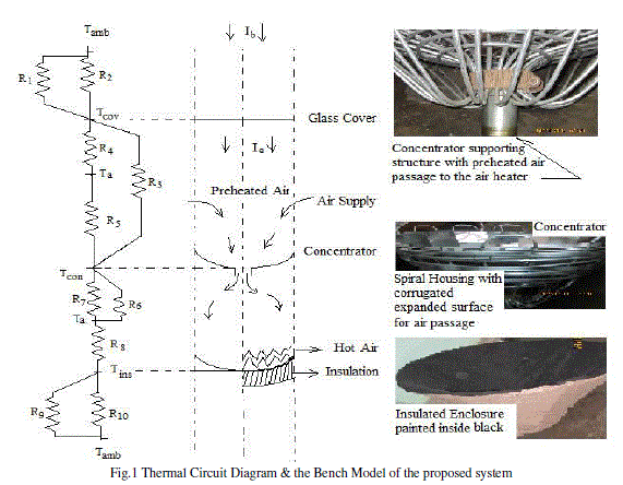
| R1 = 1/hr,cov-amb =Thermal Resistance due to the Radiative Heat Transfer Coefficient between the glazing & ambient. |
| R2 =1/hr,cov-amb =Thermal Resistance due to the Convective Heat Transfer Coefficient between the cover & ambient. |
| R3= 1/hr,con- cov= Thermal Resistance on linearised Radiative Heat Transfer Coefficient between concentrator & cover. |
| R4 =1/hc,cov-a1 =Thermal Resistance on Convective Heat Transfer Coefficient between the glazing & hot air(a1). |
| R5= 1/hc,con- a1= Thermal Resistance due to the Convective Heat Transfer Coefficient between the concentrator & hot air(a1). |
| R6 =1/hr,con- a2=Thermal Resistance due to Radiative Heat Transfer Coefficient between the concentrator & hot air(a2). |
| R7 =1/hc,con- a2=Thermal Resistance due to Convective Heat Transfer Coefficient between the concentrator & hot air(a2). |
| R8 =1/hr,ins-a2 =Thermal Resistance on Convective Heat Transfer Coefficient between Insulating enclosure & hot air(a2). |
| R9 =1/hr,ins-amb= Thermal Resistance on Radiative Heat Transfer Coefficient between the Insulating enclosure & ambient. |
| R10 =1/hc,ins-amb=Thermal Resistance for Convective Heat Transfer Coefficient between the Insulating enclosure & ambient |
| Tamb = Ambient Temperature (K) |
| Tcov = Cover Glazing Temperature(K) |
| Ta1 =Temperature of air entrapped in the space bounded by the glazing & the Concentrator (K) |
| Ta2 =Temperature of air in the space bounded by the Concentrator& the Insulating enclosure (K) |
| Tcon =Concentrator Surface Temperature (K) |
| Tins =Temperature of the Insulating enclosure (K) |
| qha1 = Heat carried away by the air from the space between the glazing & the Concentrator to the rear space (J/kg) |
| qha =Heat absorbed by hot air from the space between Concentrator rear surface & the Insulating enclosure (J/kg ) |
| Ib = Solar irradiative heat arriving at the glass cover (W/m2) |
| Ie = Effective Solar irradiative heat arriving at the concentrator surface (W/m2) |
| All thermal resistances are in (J/Kg.K)-1 |
III. THERMAL ANALYSIS |
| As referred in Fg.1, the concentrator surface made up of highly thermal conductive & optically reflective thin metallic sheet developed by Gore’s geometrical method, placed on aluminium pipe spiral housing with corrugated expanded surfaces for multiple air passages. The aperture glass cover with the focal point of the concentrator on it’s plane carries the necessary supporting system for the receiver. The concentrator rear surface along with air passage is enclosed by an insulated enclosure. The entrapped air in the space bounded by the concentrator surface & the aperture glass will be in thermal equilibrium with the air in the rear cavity bounded by the insulated enclosure & the back surface of the concentrator i.e. Ta1=Ta2=Ta. The effective solar irradiation received by the concentrator surface passing through the glass cover will thermally energize the metallic sheet as well as get focused at it’s focal point. Thus through convective & radiative mode, the entrapped air above & bellow the plate will be heated up. The upper layer having higher mass & direct solar irradiation will be in a higher thermal status than the lower layer due it’s indirect heating. Therefore arrangement is made to force the upper volume of air through the central path of the structural pivot, then through the corrugated surfaces multiple air passages of the rear enclosed space to the outlet. The temperatures of the upper & lower volumes are in equilibrium to keep the steady mass flow rate of hot air. |
 |
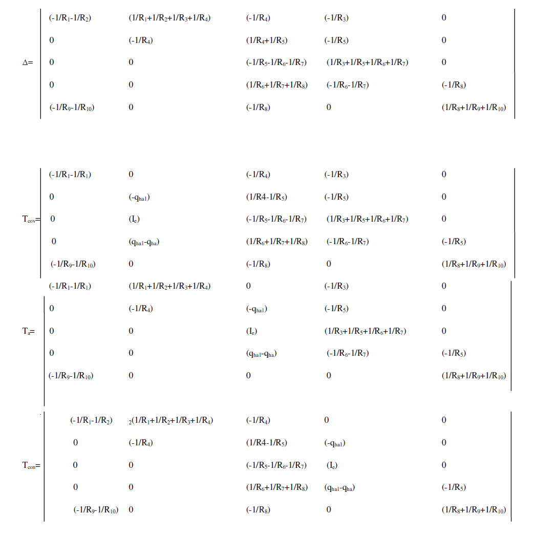
| Thermal balances at different junctions of the referred circuit at Fig.1 are as follows. |
 |
 |
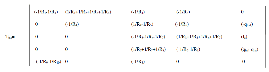 |
| However the established heat generation equation on simplification of the heat balance equations needs further simplification for a generalized expression in terms of the fin efficiency times the difference of the effective solar irradiative energy received & the overall heat loss times the ambient to outlet air temperature difference. It is depicted as Qha = F´{Ie-UL(Ta-Tamb) where F´ is the collector efficiency factor & UL is the overall heat loss coefficient considering the concentrator surface plate as the collector. |
IV. BENCH MODEL EXPERRIMENT RESULTS |
| Measuring tools used are: (i) Digital Thermometer: Range:200 to 1000 0 c (ii) Infra Red Thermometer (TESTO Make, UK) |
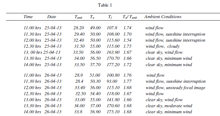 |
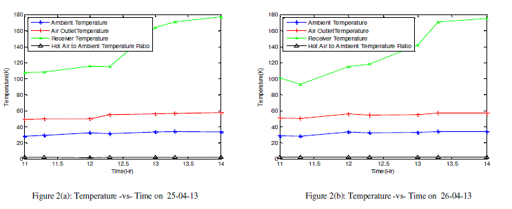
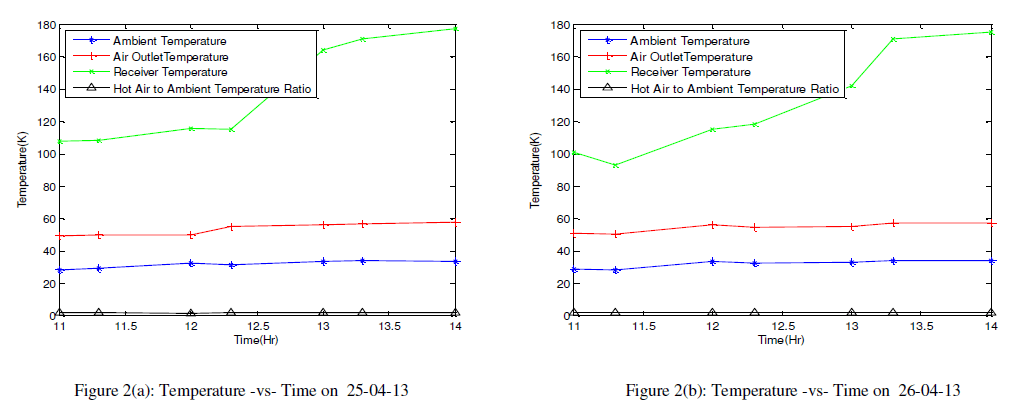
| All parameters are for 10 minutes for stagnation in every 30 minutes interval. The Ambient Temperature (Tamb), Hot Air outlet Temperature (Ta), Receiver Temperature (Tf) & the fractional increase in air temperature that of ambient, all with respect to the Time are plotted in two curves. All readings were taken in a transient period within 30 minutes under steady state condition. |
 |
V. OBSERAVTION & DISCUSSION |
| It seems that hot air gained through the concentrator plate heating on solar irradiation is additional thermal energy accessed by some system improvisation. The air heating system of low to moderate temperature requirement in any conventional system has a lower domain of temperature access. If the air temperature requirement is of multiple times that of the prevailing range, the flexibility of the conventional types e.g. flat plate or box type, glazed or unglazed air heater attributes to the alternation of it’s size, volume & other improvisations. The conventional type cannot synchronize with the variable air mass flow rate & variable temperature demand. The proposed system incorporates the waste heat recovery system along with the high temperature generation at the receiver at the focal point. Thus the temperature from ambient to moderate air temperature & from the moderate up to quite a high temperature at the focal point facilitate an wide range of temperature requirement. As such, maximum range of hot air mass flow is possible. The receiver is meant for the other heat utility, like steam of variable quality or hot water. Therefore the proposed system can be visualized as a polygeneration energy system having scope for heat reserve. |
VI. CONCLUSION |
| The average rise in air temperature becomes 1.6915 that of average ambient temperature as observed in the bench model experiment under steady state as shown in Fig.2(a) & 2(b). Definitely the resultant energy is from the waste heat recovery. This range can be elevated up to an average focal point temperature (Tf) of 1700 c if the system is used as standalone solar air heater. It implies that below the temperature Tf , the accessible amount of thermal output is possible if used as monogenerative, both hot air & hot water if as duo-generative & hot air, hot water & steam if used as a Polygenerative energy system. This may pave the way for an optimized mode of Solar Polygenerative Energy System. However the established heat equation needs further simplification for deriving the overall heat loss coefficient & the collector efficiency expressions for design optimization of the proposed model. |
ACKNOWLEDGMENT |
| This study is supported by the AICTE, MHRD, Govt of India under Research Promotion Scheme (RPS) for the core topic titled ��Simulation & Optimization of Solar Hybrid Energy Polygeneration. |
References |
 |