ISSN ONLINE(2319-8753)PRINT(2347-6710)
ISSN ONLINE(2319-8753)PRINT(2347-6710)
Shaik Waseem Ahmed1, Sudhakara Reddy.P2
|
| Related article at Pubmed, Scholar Google |
Visit for more related articles at International Journal of Innovative Research in Science, Engineering and Technology
Digital image processing(DIP) is the use of computer algorithms to perform image processing on digital images. The basic operation performed by a simple digital camera is, to convert the light energy to electrical energy, then the energy is converted to digital format and a compression algorithm is used to reduce memory requirement for storing the image. This compression algorithm is frequently called for capturing and storing the images. This leads us to develop an efficient compression algorithm which will give the same result as that of the existing algorithms with low power consumption. Image compression is useful as it helps in reduction of the usage of expensive resources, such as memory, or the transmission bandwidth required. But on the downside, compression techniques result in distortion and also additional computational resources are required for compressiondecompression of the medical image data. In this, we proposed DHT based image compression technique. The computational complexity is further reduced by using pipelined CORDIC architecture for computation of sin and cos terms in DHT. The CORDIC based DHT is partially simulated and synthesized by using Xilinx ISE design suite and the same was implemented on targeted FPGA. The hardware requirements and gate delay values are observed and noted down
Keywords |
| CORDIC, DHT, FPGA, Image Processing |
I. INTRODUCTION |
| Compression, the art and science of reducing the amount of data required to represent an image, is one of the most useful and commercially successful technologies in the field of digital image processing. Digital image and video compression is now very essential. Bio-Medical Image Compression would not be feasible unless a high degree of compression is achieved. Compression is useful as it helps in reduction of the usage of expensive resources, such as memory ( hard disks), or the transmission bandwidth required. In today’s Age of competition where everything is reducing its size every minute, the smaller is the better. But on the downside, compression techniques result in distortion and also additional computational resources are required for compression-decompression of the data. Compression ratio (C) is defined as the ratio of the size of compressed data to that of the uncompressed data. |
 |
 |
II. IMAGE PROCESSING |
| Image processing involves minimizing the size in bytes of a graphics file without degrading the quality of the image to an unacceptable level. The reduction in file size allows more images to be stored in a given amount of disk or memory space. It also reduces the time and bandwidth required for images to be sent over the Internet or downloaded from Web pages. |
| There are several different ways in which image files can be compressed. For Internet use, the two most common compressed graphic image formats are the JPEG format and the GIF for mat. The JPEG method is more often used for photographs, while the GIF method is commonly used for line art and other images in which geometric shapes are relatively simple. |
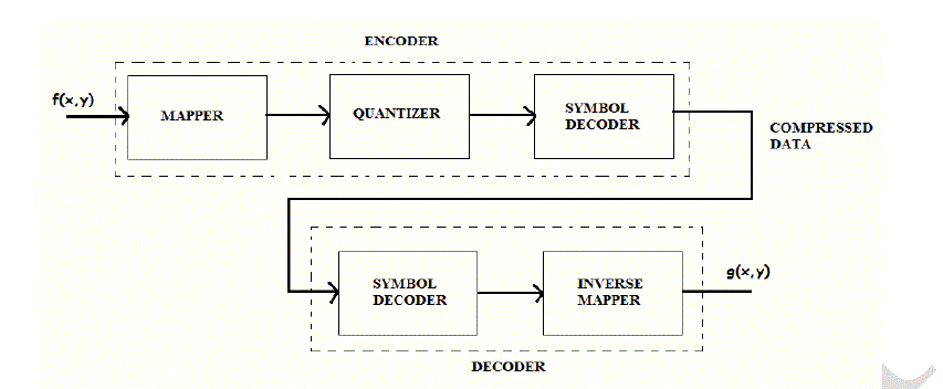
| The steps involved in image compression are as follows: |
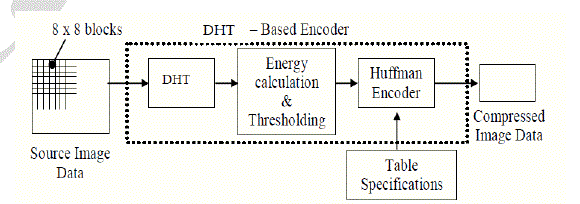
| 1. First of all the image is divided into blocks of 8x8 pixel values. These blocks are then fed to the encoder from where we obtain the compressed image. |
| 2. The next step is mapping of the pixel intensity value to another domain. The mapper transforms images into a (usually non- visual) format designed to reduce spatial and |
| 3. Temporal redundancy. It can be done by applying various transforms to the images. Here discrete Hartley transform is applied to the 8x8 blocks. |
| 4. Quantizing the transformed coefficients results in the loss of irrelevant information for the specified purpose. |
| 5. Source coding is the process of encoding information using fewer bits (or other information- bearing units) than an unencoded representation would use, through use of specific encoding schemes. |
 |
| For retrieving the image back, the steps have to be reversed from the forward process. First the data is decoded using the decoder. Next inverse transform (IDHT) is calculated to get the 8x8 blocks. These blocks are then connected to form the final image. From the reconstructed image pixel values it is clear that some of the high frequency components are preserved. This indicates that the edge property of the image is preserved. |
 |
III. MATHEMATICAL REPRESENTATION OF DHT |
| The Hartley transform is an integral transform closely related to the Fourier transform, but which transforms real- valued functions to real-valued functions. It was proposed as an alternative to the Fourier transform by R. V. L. Hartley in 1942. Compared to the Fourier transform, the Hartley transform has the advantages of transforming real functions to real functions and of being its own inverse. The discrete version of the transform, the Discrete Hartley transform, was introduced by R. N. Bracewell in 1983. Discrete Hartley Transform is the real valued transform which gives only real transform coefficients for real input stream. It has the main advantage over DCT of reducing the memory content up to 50% since the inverse transform is identical to the forward transform. Also, it retains the higher frequency components, which restores the detailing of the image. Since it is a real valued function unlike DFT, the computational complexities are also lower than in DFT algorithms [2]. |
 |
IV. 8-POINT DHT SIGNAL FLOW |
 |
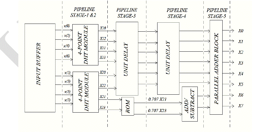 |
| So, for computing 8-point DHT the multiplication with 1/ 2 can be read from a ROM, while a block of pipelined |
 |
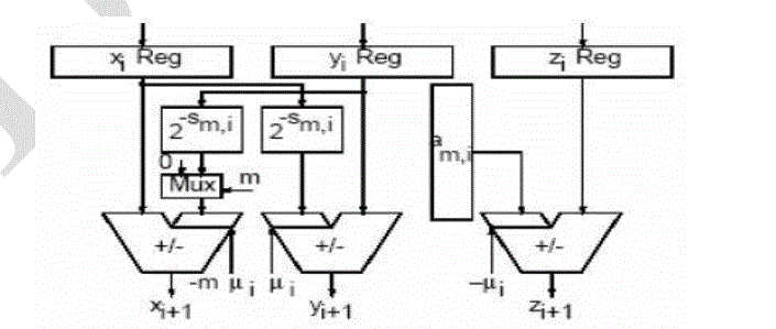 |
| The figure 5 shows the structure of a processing element which implements one CORDIC iteration the rotation mode and vectoring mode are two schemes for the CORDIC algorithm. In rotation mode, the aim is to rotate the given input vector (ïÿýïÿý , ïÿýïÿý)ïÿýïÿý with a given angle. After n no’s of iterations, ïÿýïÿýïÿýïÿý is driven to zero and the total accumulated rotation angle is equal to desired angle Parallel pipelined architecture for CORDIC represents a version of the sequential CORDIC algorithm. Instead of reusing the same hardware for all iteration stages, the parallel architecture provides a separate processor for every iteration. |
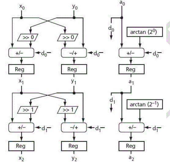 |
| An example of the parallel CORDIC architecture for rotation mode is shown in figure 6. Each of the n processors present in the block performs a specific iteration, and a particular processor always performs the same iteration. All the shifters perform the fixed shift, so that it can be implemented in FPGA.[5] Every processor utilizes a individual arc tan value that can also be hardwired to the input of every angle accumulator in the absence of a state machine which provides simplicity to this type of architecture. The parallel architecture is much faster than the sequential architecture described in the “iterative Word-serial architecture” in figure 6. It takes new input data and puts out the results at every clock cycle, introducing a latency of n clock cycles. The architecture which is used in the design of the DHT is this parallel-pipelined architecture because this architecture which provides high throughput and low power consumption. Then we can apply the above conditions to the DHT equation. |
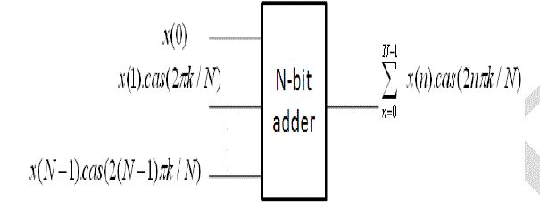
| The DHT is given |
 |
 |
 |
 |
VI. RESULTS ANALYSIS AND IMPLEMENTATION |
| The real and imaginary parts of the Fourier transform are given by the even and odd parts of the Hartley transform, respectively |
 |
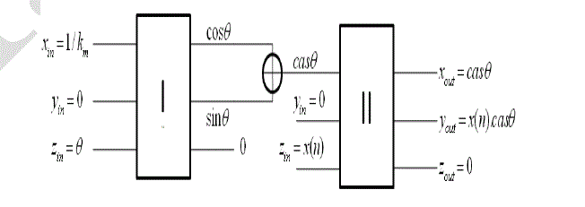
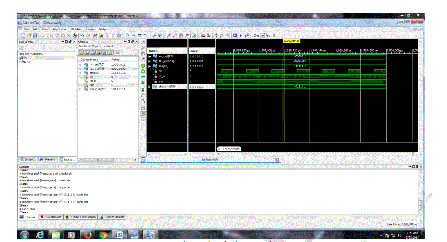
| Initially the DHT was decomposed in terms of COS and SINE terms by using Euler’s formula, then for the computation of these trigonometric components we use CORDIC processor. For hardware implementation, we developed Verilog code and compiled using ModelSim software. Further simulated and synthesized by using Xilinx ISE design suite version 12.0 and implemented on Spartan 6.0 FPGA. Finally synthesis report and delay report are noted down. From the results it is observed that, the total real time taken for execution is 1.00secs, the total CPU time taken for execution is 0.94 sec. The macro statistics of CORDIC requires only single ROM, one 4x8-bit ROM, 20-adders and subtractions, three 8-bit adders, one 8-bit subtraction, 32 registers, eight 2-bit registers, 24 8-bit registers and 2 – multiplexers. The simulation results are as shown in figure 9. |
 |
VII. CONCLUSION |
| In the present work, Discrete Hartley Transform for input matrix was implemented in FPGA using VHDL as the synthesis tool. The DHT was also calculated for 8-point input using two algorithms and their effectiveness were discussed, this primarily focuses on image compression with less computation and low power. The simulation results and design summary of DHT was obtained and it was shown that the architecture implemented is an efficient method which uses limited space and time. The hardware utilization is quite optimum and power analysis shows that the power requirement is also optimum. However if the input contents are large, they tend to overflow from the registers and hence error occurs. It can be rectified by saving the transformed coefficients in larger registers. Also due to quantization in the contents of the ROM, even-number outputs are more deviated from the desired results than the odd-numbered outputs. |
References |
|