ISSN ONLINE(2319-8753)PRINT(2347-6710)
ISSN ONLINE(2319-8753)PRINT(2347-6710)
J.Christysudha1, T.Anuradha2
|
| Related article at Pubmed, Scholar Google |
Visit for more related articles at International Journal of Innovative Research in Science, Engineering and Technology
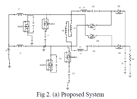
In this paper a novel topology of interleaved ZVS and the concept of built-in transformer voltage doubler cell with PWM boost converter is presented. Now-a-days with the inadequacy in energy and continually enlarging fuel cost, investigation on the renewable energy becomes more and more important. Different traditional converters like boost converters, switched capacitors and coupled inductor based converter tolerate high transient current and conduction losses as the switching frequency is varied. In the proposed system the two implemented tractable variations in switch duty cycle and transformer turns ratio raises the voltage gain flexibly. The reverse recovery losses of the diodes is diminished and lessens the input current ripple and output voltage ripple by employing soft switching technique. This schemed controller utilizes PWM techniques to regulate the output power of boost converter at its maximum value; moreover active clamp scheme is maintained which incorporates switch turn-off voltage spikes and accomplishes ZVS operation for all switches. This paper presents the design method for DC to DC converter with increase in voltage gain by reducing voltage stresses of diodes thereby providing high efficiency and high step up conversion which is applicable for renewable energy sources.
Keywords |
| dc to dc converter, interleaved, soft switching, renewable energy, zero voltage switching |
INTRODUCTION |
| The massive consumption of a natural fuel such as the oil, the coal and the gas pollutes atmosphere and results in serious green house effect on the world. On the other hand, there is a huge denial in the middle of the fossil fuels supply and the global energy demand. Some limitations for the human development have been maximized as energy shortage and the atmosphere pollution. So the recyclable source of renewable energy source wind, solar wave can be selected for high step-up operation. Renewable energy resources are being replaced and generated at the same ate that are being utilized. |
| The renewable energy sources are considered to be environmentally friendly and harness natural process [3]. These sources can provide an alternate cleaner source of energy helps to negate the certain forms of pollution and they are not depleting any source of energy during power generation are also suited to small off grid applications, |
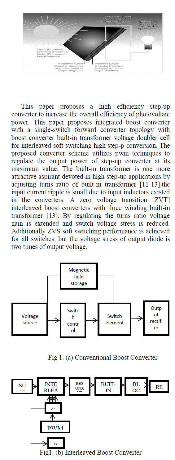
| Sometimes in rural and remote areas where energy is often crucial in human development. Generally the applications of high step-up dc-dc converter involves the following requirements as high step-up voltage gain, low input current and output voltage ripple, high current handling capability and high efficiency. The conventional coupled inductor and switched capacitor based converters perceive high step-up gain because the turns ratio of the coupled inductor can be engage as various control freedom to boost the voltage gain [4-10]. In anyway, the input current ripple is comparably large by employing single-stage single phase coupled inductor-based converters, which compress the activity of the input electrolytic capacitor. Photovoltaic source is the main electricity renewable energy source, it is the world‟s largest electricity generating, emission free and highly reliable source |
 |
| To overcome the above problem of traditional converter, the concept of built-in transformer voltage doubler cell is derived by inquiring detailed operation of three winding built-in transformer. The additional voltage doublercapacitors can be charged or discharged alternatively to double the voltage gain. Both the switch duty cycle and the transformer turns ratio are employed as two controllable freedoms to lift the voltage ratio, Due to the built-in transformer voltage doubler cell, voltage stress of the diode and switches can also be minimized, and possible to make low rated power devices practicable to improve the circuit performance in high step-up and high current conversion system. This paper is devoted to a new power circuit topology to be implemented with voltage doubler cell to provide effective high step-up in the whole range of input and turns ratio variations. The proposed converter has the following advantages: |
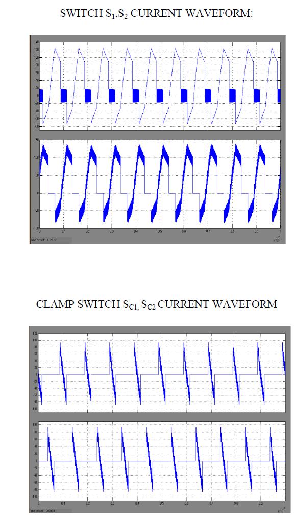
| - The converter can able to turn on both the active power switches at zero voltage to reduce their switching losses and evidently raise their conversion efficiency with very fast tracking speed. |
| - Output voltage stress of switches and diodes is reduced |
| - Reverse recovery losses of diodes is alleviated by the leakage inductance of built-in transformer |
| - Due to the operation of interleaved structure current ripples is eliminated |
| - Extendibility to desired voltage gain and power level |
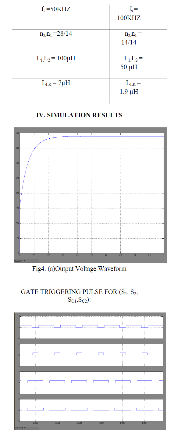
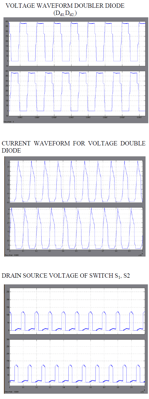
| The experimental result is verified with 96% efficiency using MATLAB-SIMULINK and this can be implemented in photovoltaic cell for better high step-up conversion. |
PROPOSED INTERLEAVED BUILT-IN TRANSFORMER VOLTAGE DOUBLER CELL |
| Compared with the original converter with three winding transformer, due to the built-in transformer voltage doubler cell, the voltage stresses of the switches and the diode can also be reduced, which makes the low voltage-rated power devices practicable to improve the circuit performance. The additional voltage doubler capacitors can be charged or discharged alternatively to double the voltage gain. Both the switch duty cycle and the transformer turns ratio are employed as two controllable freedoms to lift the voltage ratio. These factors further improved the circuit performance in the high step-up and large current conversion system. |
 |
PRINCIPLE ANALYSIS OF PROPOSED CONVERTER |
| The interleaved structure is an effective solution to improve the power level and minimize the current ripple [13]. A two interleaved boost converter is derived by removing the transformer [14]. An auxiliary transformer with a unity turns ratio is employed to couple the current paths of the inductors and to achieve the current auto-sharing performance. The output voltage can be managed from full load to practically no load as a result of current -mirror effect of complementary transformer. However the converter operates in hard switching performance .A family of interleaved high stepup boost converter with winding-cross-coupled inductors (WCCIS) [15-18] which can reach intensely high step-up conversion and reduce the switch voltage stress. The active clamp circuits and the passive lossless clamp circuits can be approved to achieve ZVS or ZCS soft switching performance. The main limitation of high stepup converter with WCCIS that each WCCI has three windings is strenuous for the industrial manufacture. |
| A. Design Considerations: |
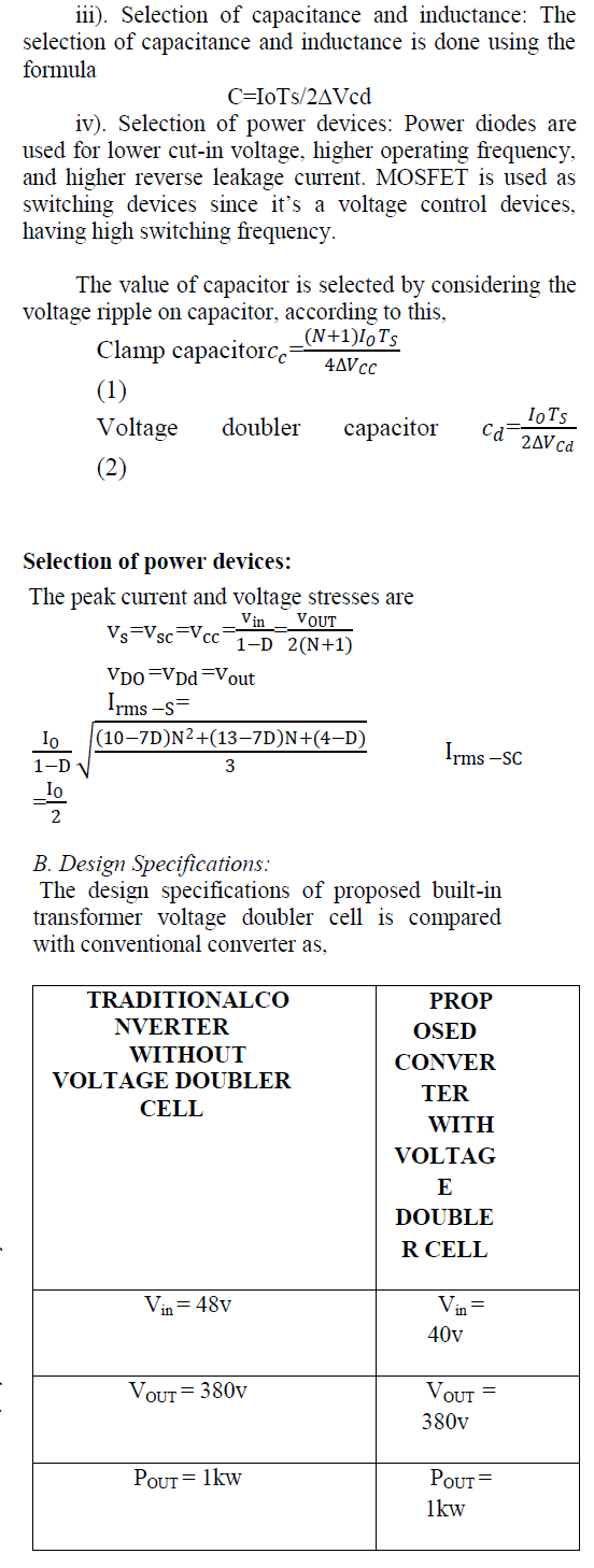
| This interleaved converter with built-in transformer voltage doubler cell involves the selection of number of phases, the inductors, the power switches and the output diodes. Both the inductors and diodes should be identical in all channel of an interleaved design. In order to select these components, it is necessary to know the duty cycle range and peak currents. Since the output power is channeled through „n‟ power paths where „n‟ is the number of phases. |
| i). Choosing the number of phases: if the number of the phases is increased further, without much decrease in the ripple content, the complexity of the circuit very much, thereby increasing the cost of implementation. Hence as a trade of between the ripple content and cost and complexity, number of phases is chosen. The number of inductor, switches and diodes are same as the number of phases and switching frequency is same as all the phases. |
| ii). Selection of duty cycle: the decision of the duty cycle is based on the number of phases. This is because depending upon the number of phases ripples is a minimum at a certain duty cycle. |
 |
 |
 |
 |
CONCLUSION |
| This paper successfully presents the built-in transformer voltage doubler cell with 1kw dc-dc converter is designed for PV system was built based on this method. Due to the high step-up conversion can be used to draw the maximum power from PV arrays provides reliable high efficient power conversion. The proposed converter with voltage doubler cell reduces voltage stresses at turn off transition. Therefore the conversion efficiency of proposed system increased efficiently; furthermore from the experimental efficiency of proposed converter it has been shown that the proposed converter can yield high efficiency under heavy load conditions. |
References |
|