ISSN ONLINE(2319-8753)PRINT(2347-6710)
ISSN ONLINE(2319-8753)PRINT(2347-6710)
K.P. Patil 1, Prof V. R. Gambhire.2
|
| Related article at Pubmed, Scholar Google |
Visit for more related articles at International Journal of Innovative Research in Science, Engineering and Technology
A Cam-based Infinitely Variable Transmission is a type of transmission that allows an infinitely variable ratio change within a finite range, allowing the engine to continuously operate in an efficient or high performance range. A Cam-based Infinitely Variable Transmission system is a drive mechanism with one set of planetary gears & a cam with three followers mounted on carrier. The followers can be shifted in relation to the three dimensional cam by shifter mechanism due to which followers oscillation magnitude changes. The one way clutch use to transfer positive motion of follower to planet gear. The mechanism adapted for infinitely variable output between range 0 to1/4th of input speed. It maintains a uniform output for a given uniform input.
Keywords |
| Infinitely Variable Transmission (IVT), Continuously Variable Transmission, Positive Transmission. |
INTRODUCTION |
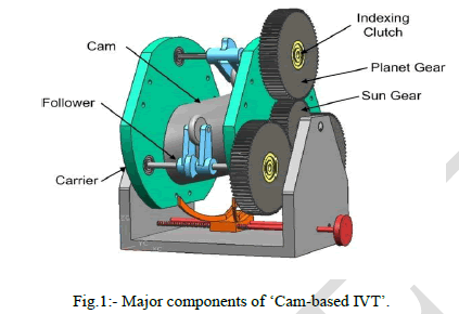
| This transmission contains six unique components. The heart of this transmission is a centrally located three dimensional cam. Cam has a continuously varying profile along its length. Around the cam there are three number of followers. Each follower interacts with the cam through a roller mounted on follower. The followers are held to the cam surface when not under load by a return spring. The followers are rotatably mounted on one carrier plates, the major unique component of the transmission. The carriers are used to support the followers. On each follower, there is fixed planet gear which meshes with a sun gear. The sixth and final unique component of the Cam-based IVT is a one way clutch located inside each of the planet gears. These clutches are responsible for rectifying the oscillations generated by the cam and followers. The one way clutch transmits only positive motion. The planet gears are meshed with a sun gear. The three planet gears output combines in a sun gear & which gives output. A Cam-based Infinitely Variable Transmission system allows a user to vary the speed between input & output progressively from one positive value to another. Unlike, conventional transmissions the selection of gears is not restricted to a finite number of ratios. The Cam-based Infinitely Variable Transmission system can be used in industrial drive applications to improve performance, economy & functionality. |
II. LITERATURE REVIEW |
| The prior work in Infinitely Variable Transmission System by using Ratcheting drives by Benitez [1] he presents a transmission whose characterized by its non-uniform output for a uniform input. It is similar in that there is a device that varies the amount of rotation of several planetary gears with respect to a carrier. This particular design uses a slotted plate to drive a number of planet gears around a sun gear. By varying the eccentricity, e, of the slotted plate with respect to the "guide groove", the angular velocity of the planet gears will vary as they travel around the sun. Each planet gear is connected to a second planet through a one way clutch; the planet with the largest velocity will then transmit motion to the ring gear. Similarly, Pires [2] incorporates a number of levers, shafts, and a slotted plate to accomplish the same task. Similar in concept to both Pires and Benitez, but different in implementation is a design used by Matsumoto [3], which is commercially available under the name "Zero-Max". This transmission uses several reciprocating four bar linkages to oscillate the indexing clutches. One of the several linkage systems. An input is applied to the crank mechanism on the left which oscillates the first four bar mechanism. A second four bar loop converts these oscillations to a continuous output rotation through a number of one way clutches. Like BenitezâÂÂs and Pires' CVTs though, it exhibits a non-uniform output for a uniform input. In the same vein as other ratcheting drives, Douglas Magyari [4] develop an Infinitely Variable Transmission comprising a pair of rotary, generally conical, torque-transmitting members, each being mounted for rotation on its geometric axis, the angularity of axes, one with respect to the other, being variable, the outer surfaces of each member having torque transmitting needles extending outwardly from the generally conical surface, the needles of one member meshing with the needles of its companion member, the needles being capable of flexing whereby torque may be transmitted through the rotary members without frictional sliding motion at the area of meshing engagement of the needles, the angularity of one member with respect to the other permitting a wide torque transmitting ratio range. Similarly, for improving torque transmitting capacity Peter Eichenberger [5] has worked which having a driving sheave assembly connected to the crankshaft of an internal combustion engine and coaxially mounted with respect to the crankshaft, an intermediate shaft upon which is mounted a driven pulley assembly, a drive chain or belt drivable connected the pulley assemblies, high range and low range gearing coaxially disposed with respect to the driven pulley assembly, a countershaft arranged in parallel and spaced disposition with respect to the secondary shaft wherein the countershaft is adapted to support forward and reverse gearing and improved bearing means for supporting the countershaft and wherein a differential output assembly connects torque output elements of the countershaft to each of two axle half shafts thus providing improved torque transmitting capacity with reduced overall dimensions due to the reduced shaft spacing. Wayne Paul Bishop [6] has worked on Infinitely Variable Transmission by using Forced Way method. This is a unique method of generating variable ratio outputs from a given input of constant rotational speed by forcing one end of a drive shaft to follow a continuous path (way) around a given circle at a constant speed that can then be deformed into curves of varying radiuses that would range from the radius of the given circle to that of the various radiuses (arcs) of various ovals to a final shape of an oblong. Forcing the end of the drive shaft to follow these shapes would result in the driveshaft rotating at different rotational speeds as it transverses the shape. By sampling only the rotational output while moving over the desired portion of the shape one can control the outputs rotational speed which will be some ratio of the input. |
III. BASIC THEORY OF THE CAM BASED INFINITELY VARIABLE TRANSMISSION SYSTEM |
| Principle:- This Infinitely Variable Transmission system convert uniform motion to oscillating motion, and then rectify it back to an almost uniform motion. Firstly, there is a mechanism that produces oscillating motion from rotational input. This mechanism allows adjustable oscillating stroke. Secondly, the reciprocating motion is rectified by a mechanism such as a one-way-clutch (or freewheel). Thus, the reciprocating motion is rectified to a unidirectional rotational output. It is possible to adjust the speed of this rotational output simply by adjusting the oscillating stroke. To obtain a smoother output motion, three out-ofphase followers are used. In its simplest form, this transmission contains six unique components. Each component is described here briefly and illustrated in the following figures. While their function may be explain here. The heart of this transmission is a centrally located three dimensional cam. Cam has a continuously varying profile along its length. Around the cam there are three number of followers. Each follower interacts with the cam through a roller mounted on follower. The followers are held to the cam surface when not under load by a return spring. The followers are rotatably mounted on a carrier plate, the third major unique component of the transmission. The carrier plate is used to support the followers as well as change the location of follower with the help of shifter mechanism. On each follower, there is fixed planet gear which meshes with a sun gear. The sixth and final unique component of the Cam-based IVT is a one way clutch located inside each of the planet gears. These clutches are responsible for rectifying the oscillations generated by the cam and followers. The shaft connected to this inner race of the sun gears is simply called the sun gear shaft or output shaft and its sole purpose is to transmit torques from planet gear to sun gears (however usually not at the same time). The one way clutches are located in the planet gears, the sun shaft is directly connected to only one sun gear. These components are labelled on a simplified representation of prototype CAD model in Figure 1. |
 |
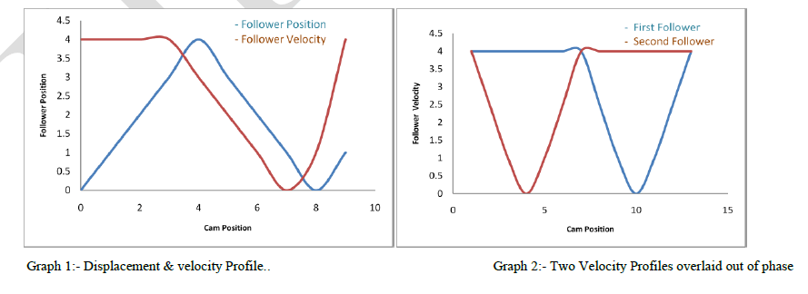
| The Cam-based IVT which can be thought of as simply a cam and follower system with an attached gear train. Therefore the cam will serve as the input and the sun gear shaft as the output while the carriers remain fixed to ground. In such a configuration, a rotational input to the cam causes the followers to simply oscillate up and down as they are held to the cam with the return springs. In this case the followers do not rotate around the cam because the carrier is fixed. Due to the shape of the cam and the position of the followers around the cam, the followers oscillate out of phase of one another, that is, one follower will rotate clockwise, while the other rotates predominately counter clockwise. The out of phase oscillations of the followers drives the their respective planet gears back and forth. It follows then that one direction of the oscillations of the planet gears will be transmitted to the sun gear shaft through the one way clutches. Because one planet gear will always be moving faster in the locking direction of the clutches, one planet will transmit torque to the sun gear shaft. With a carefully designed cam profile, the velocity of the planet gears can be shaped to produce a smooth and continuous output of the sun gear shaft with no velocity ripples. Such a velocity profile would look something like that in Graph 1. When overlaid with the velocity Profile of the other out of phase followers, it would appear as in Graph 2. Graph |
 |
| It provides higher gear ratios as well as a larger gear ratio range for a given cam eccentricity. It has been experienced that this is more difficult to visualize than others, but much clarity can be gained by picturing something similar and much more familiar, a planetary gearset. To fully describe its motion, first a circular cam is considered. This will decouple the motion of the carrier and the followers around the cam, from the oscillations of the followers. Once these dynamics are understood, it is only a small step to superimpose follower oscillations and their effects on the carrier motion to understand the full system. To begin, first consider a perfectly circular cam. A clockwise rotation applied to the cam is transmitted by all one way clutches as a counter clockwise rotation on the planet gears, but followers are not oscillate due to circular cam shape. Hence speed will not be transfer to sun gear i.e. output shaft through one way clutch. Now consider a non-circular cam. The operation is nearly the same as above, a clockwise rotation of the cam forces the followers to oscillate due to non-circular shape of the cam. The one way clutch rotate the planet gear in counter clockwise direction. The planet gears are meshes with sun gear i.e. output gear. The sun gear rotates clockwise with reduced speed. The output speed of gear depends upon the position of the follower on non-circular cam. There will be only one follower was considered in the above analysis. This follower, the one under load, is called the active follower. This is because while the active follower is moving up a cam lobe, the second or third followers, called the inactive followers, should be moving down a lobe and will be rotating in a counter clockwise direction with respect to the carrier as a result. A counter clockwise rotation of the attached planet gear will rotate the meshing sun gear further clockwise, in a direction that disengages the one way clutch, Because the sun gear shaft rotates clockwise, they are installed such that they lock up with a counter clockwise application of torque on the sun gear race. Therefore as one planet gear transmits torque to the sun gear, the second is freewheeling faster in the same direction, but one gear is always engaged with the sun gear shaft. |
IV. KINEMATIC SYNTHESIS OF CAM PROFILE AND SPEED CHANGE MECHANISM FOR OPTIMIZED OUTPUT |
| The behaviour of the transmission is highly dependent on the cam profile. This profile combines a constant velocity section. The acting planet is the planet gear that is driving the output, it is often the planet gear with the maximum rotational velocity with respect to the carrier at that time. It may also the planet gear with the largest velocity in the driving direction, the direction in which the one way clutches engage. The portion of the cam profile on which a followers, and therefore planet gears, are active is called the acting profile. The cam rotates in 3600, for reduction of speed by 1/4th the cumulative lift of all active followers for one cycle will be 900. Therefore it is the sum of all followers rotations during the active profile of the cam for one cycle of the followers around the cam. Hence for one followers motion equal to 900 divided by the number of followers. The number of followers is three so every follower should be oscillate by 300. The position and velocity curve of the cam follower is as shown in Graph 3. |
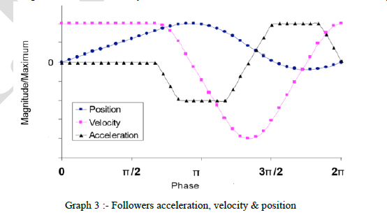 |
| The follower acceleration curve is trapezoidal type hence acceleration is constant when follower is raising hence velocity also constant. Velocity and acceleration continuously decreasing when follower position lowering. The acceleration and velocity curve depends on position of follower. |
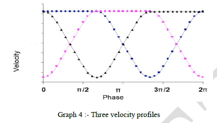 |
| The three followers velocity profiles for transmission are overlaid with an offset as shown in graph 4. The followers oscillate in the same direction of the cam as it rotates. The all followers velocity are constant for the acting profile. When the follower is rising on cam profile the velocity is constant and as the follower position lowering the velocity decreases suddenly. At a time one follower is in rising, as it lowering same time another follower is rising so the output velocity is maintain constant without oscillations. The sun gear is centrally located, it will rotate causes planet gear. This operation is similar to the cam and follower arrangement of the cam based IVT and therefore the cam and follower system can be modelled as a geartrain. The cam is centrally located, and when rotated, causes at least one follower to rotate in a direction that engages the clutches. The relationship of gear ratio of pair of sun and planet gears with an effective ratio between the followers and the cam. This effective ratio captures the interaction between the cam and followers during the active profile. This effective ratio is essentially the collective amount of the followers rotate in one direction for every revolution about the cam is four and is therefore analogous to the gear ratio. |
V. TEST & TRIAL ON CBIVT |
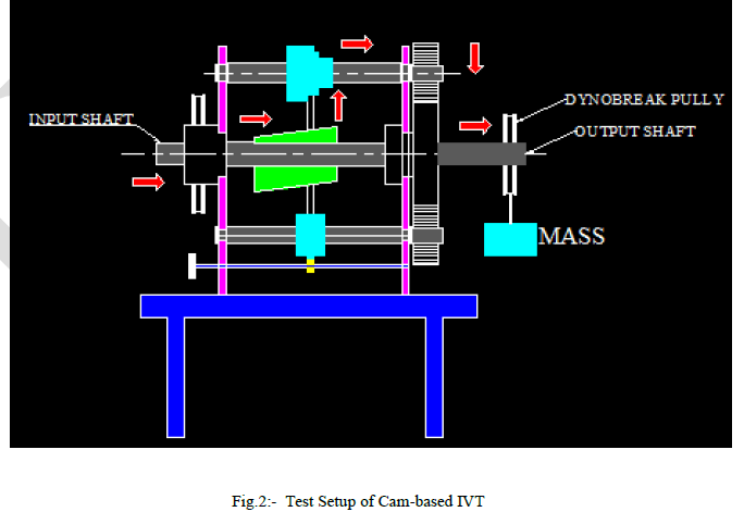 |
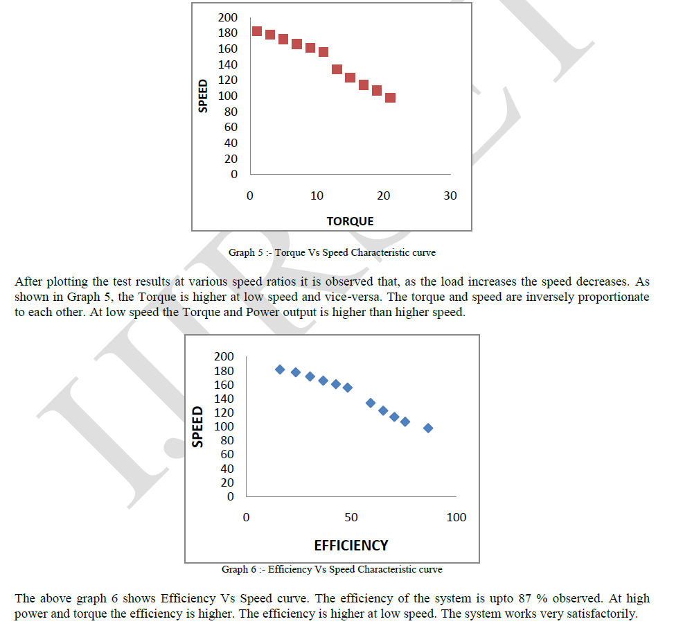
| Trial is to be conducted on Cam-based Infinitely Variable Transmission System to determine various characteristics like Torque Vs Speed, Power Vs Speed and Efficiency. The trial is conduct by using rope brake dynamo meter, pulley, cord, weight pan are provided on the output shaft. Testing Procedure:- The Electric motor is used as input source, using electronic speed variator knob let mechanism run & stabilize at certain speed. On the output shaft place the pulley cord on dynobrake pulley and add 100 gm weight into the pan, note down the output speed for this load with the help of tachometer. Add another 100 gm weight into pan & take readings. Tabulate the readings in the observation table. Calculate the Power, Torque characteristics. Testing Results :- |
 |
| Applications :- Speed drives for machine tool spindles :- Machine tool spindles are required to be driven out various speeds depending upon size of work & material to be cut. In such cases the Cam-based Infinitely Variable Transmission system can be used along with the head stock to give an infinitely variable speed. Feed drives for machine tool slides :- Machine tool slides can be moved at different speeds to impart feeding motion to the cutting tool using this Cam-based Infinitely Variable Transmission system. Variable speed drive for Conveyors in assembly line of automatic assembly plants.Variable speed drive in automatic transfer links & pick & place type Robotic devices.Bottle filling plants. Indexing mechanism in automats. |
VI. CONCLUSION |
| The Cam-based Infinitely Variable Transmission system gives the variable speed ratios. It is new advancement on the conventional gear box. The Cam-based IVT allows the attached devices to rotate completely independent speed ratio due to which efficiency of both attached devices increases. The Cam-based IVT gives output speed in between zero to 1/4th of the input speed. Uniform output is one more unique ability this system. Cam-based IVT system having very reliable technology and the model is having maximum efficiency 87%. It is very clean, low weight and compact instrument. |
References |
|