International Journal of Innovative Research in Science, Engineering and Technology
ISSN ONLINE(2319-8753)PRINT(2347-6710)
ISSN ONLINE(2319-8753)PRINT(2347-6710)
R.M.Sasiraja1, Dr.V.Suresh Kumar2, S.Ponmani3
|
| Related article at Pubmed, Scholar Google |
Visit for more related articles at International Journal of Innovative Research in Science, Engineering and Technology
In power system, unexpected outages of generation, sudden increase of demand, tripping of transmission lines, or failures of other equipment have led to congestion in one or more transmission lines. The network loading is maintained within the specified norms for system secure operation. Generation rescheduling and/or load shedding can relive the non-severe congestion and the severe congestion has to be relieved by some improved method. With the wide application of distributed generation (DG) sourcecongestion management is done by optimumplacement of DG in the distribution network.As it is known that non-optimal size and non-optimal placement of DG units may lead to high power loss and bad voltage profiles, therefore, this paper uses, Line Flow Sensitivity Factor (LFSF) analysis to determine the optimal location of DG units, as well as Genetic Algorithm (GA) for determining the optimal size of DG in distribution systems. A multi-objective function is created to minimize the total losses and improve the voltage profile of the distribution system.This methodology is tested on IEEE-30 bus system. The optimal placement and sizing of DG was found to be robust and provided higher efficiency for the improvement of the voltage profile and minimization of losses.
Keywords |
| Congestion, Performance Index, LFSF, DG, GA. |
INTRODUCTION |
| Transmission line congestion is the one of the major issues in deregulation of power industry. Forcing the electric utilities to increase their generation leads to meeting the universal demand for electric power. Congestion occurs whenever one or more constraints are violated under which the system operates in the “normal” state or in any of the contingency cases in a list of specified contingencies. The contingency constraints can either be physical limits like thermal or voltage limits or specified limits to ensure system security and reliability. The transmission lines or transformers’ overloading condition is called congestion.There are several methods to relieve congestion, such as using re-dispatching power generation, flexible ac transmission system, tapping transformers, curtailing poor loads and/or bilateral contracts.A fast relief of congestion may be possible byremoving congested lines to prevent severe damages to the system. In a deregulated environment, all the Generating Companies (GENCOs) and Distribution Companies (DISCOs) plan their transactions ahead of time. However, by the time of implementation of transactions, congestion may already be present in some of the transmission lines. |
| The system retain in its secure state, as ISO relieve the congestion. ISO mainly uses two types of techniques to relieve congestion. |
| These are listed below |
| 1. Cost free means |
| a. Out-aging of congested lines |
| b. Operation of transformer taps/phase shifters |
| c. Placing DGs in a distribution network |
| 2. Non-cost free means |
| a. Carrying out re-dispatching power generation in a variant method from the natural settling point of the market. It backs down certain generators, while the output increases in the other. Consequently, no longer the generators operate at equal incremental costs. |
| b. Load curtailment and the exercise of (non-cost free) load interruption options. |
| Breaking away from the earlier paradigm of electricity generation, transmission and consumptionDistributed Generations (DGs) does mean a DG,it does refers to the small scale electric power generators dispersed within distribution network level whether located on the customer side or an isolated site not connected to the power grid. Currently, there areseveral kinds of DGs [1], such as diesel turbines with the capacity under 1 MW, gas turbines with the capacity in the range of 1– 20 MW, micro turbines range from 30 to 200 kW, and hydro generation capacity in the range of 100 kW–1 MW. It is expected that DGs will cover 25% of the load increase in the coming 10 years in North America [2]. In [3-6], it is shown that in some cases, the control of load demand can be more effective than rescheduling of generator in case of congestion. |
| In paper [7] a direct method of determining a generation rescheduling and load shedding pattern to alleviate line overloads is developed. The basic and decoupled line overload alleviation models consisting of a set of linear relationships between line currents and state variables, and between bus power injections and state variables are developed. Algorithms for solving these mathematical models in conjunction with the Newton- Raphson and decoupled load flow models are also described. It is believed that these techniques will be useful in system security studies, reliability studies, operational planning and load dispatch. However minimization of the cost of generation under feasible operating condition is computationally expensive.Relative Electrical Distance (RED) concept is used to optimize generator rescheduling in order to relieve congestion [8]. Relative electrical distance concept is reliable and fast to determined congested lines. In Relative Electrical Distance concept, relative location of the load nodes is found with respect to the generator nodes. |
| In paper [9] over load alleviation in deregulated transmission line is explored with real coded genetic algorithm (RCGA) is an efficient method to find the optimal generation rescheduling for relieving congestion. It operates on floating point representation of variables to be optimized. Furthermore the line overloads are relieved by generator rescheduling alone without any load curtailment.In paper [10] a multiple-criteria approach is proposed for managing transmission congestion in a deregulated system. In the pool model peak locational price resulting from transmission congestion is determined by marginal costs of optimal power flow solutions. Curtailing a small portion of the non-firm transactions can relieve the heavy physical transmission congestion; thereby the resultant electricity prices of marginal-cost-based decreases drastically. Both load and supplier can express their acceptance level with the congestion relief process, andeffective and desirable congestion relief measures are then taken system operator by introducing multi -criteria performance indices. |
| For reduction in the transmission congestion and for better utilization of the existing grid infrastructure, placement of series FACTS devices (TCSC) [11] based on LMP differences and congestion cost is the efficient technology. This methodcannot capture the non-linearity associated with the system and the other issues such as device proper location, appropriate size and setting, cost, modeling and controller interactions are not concerned. In paper [12] an attempt is made to relieve the system congestion by generation rescheduling alone if not relieved FACTS devices are considered. Generation rescheduling and/or load shedding is carried out using Evolutionary Programming and Particle Swarm Optimization techniques for the optimal location and sizing of multiple TCSC. |
| Application of deregulation in the power sector has identified a new electric power system map known as “distributed generation” (DG) sized from kW to MW at load sits instead of using traditional centralized generation units sized from 100MW to GW which is located far from the loads where the natural recourses are available. In [13] some important definitions of DGs and their operational constraints are discussed in details. |
| For obtaining the maximum potential benefits proper location of DGs in power systems is crucial. In paper [14] the optimal location for placing DGis to minimize the power loss. Further it is not an iterative procedure like power flow algorithm and the optimal DG size is not considered.In an optimal power flow (OPF) based wholesale electricity market the optimal placement of distributed generation (DG)on the basis of locational marginal price (LMP) is identified in paper [15]. |
 |
| In the present work, determination of sitting of DGs for congestion management under sever contingency have been proposed. It is known that non-optimal placement of DG units may lead to high power loss and bad voltage profiles. Therefore, this paper uses, Line Flow Sensitivity Factor (LFSF) analysis to determine the optimal location of DG units in meshed distribution systems. Place DG in suitable location again performs load flow and N-1 contingency criteria. It seems that the method can aid the independent system operator to reduce the line overloading in both normal and contingency conditions in an optimal manner. |
II. PROBLEM FORMULATION |
| DG allocation for congestion management considering the (N-1) contingency criteria will have more impact on system from security point of view. A suitable allocation will be that which would give better performance in most of the operating conditions. Contingency ranking has been carried out using voltage security and power flow performance indices. |
A. Contingency Selection |
| Contingency analysis has been carried out to assess the impactof severe contingencies on the system security and to alert the system operators about the critical contingencies that violate theequipment operating limits. The most common limit violations include transmission line and/or transformer thermal overloads and inadequate voltage levels at system buses. Given this information, a system operator can judge the relative severity of each contingency and decide if preventive actions should be initiated to mitigate the potential problems [16]. |
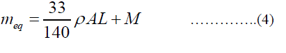
| The general performance index for a system is defined as, |
 |
| Where and are the weighting factors of line-l and bus-j respectively that is decided by the system operator depending upon the operating condition of the system,is the line flow in lthline with ithoutage, is the rated capacity of line, N is the total number of buses in the system, 2n represents the order of performance index, |
| is the voltage at bus j with ithoutage. Also considering the value of exponent as 2 and , =2. As various possible outages create a contingency set and for some cases in the contingency set may guide to congestion problems during power system operations. Such critical contingencies should be quickly identified for further detailed evaluation for corrective measures. The process of identifying these critical contingencies is referred to as contingency Selection. Contingency selection identifies the critical contingencies among them and ranks them in order of their severity. |
B. Allocation of DGs using Sensitivity Factors |
| In the market environment, generators and distributors trade electric energy. Sensitivity of the power flow on the congested line will be different with respect to the generator and load buses in the system under consideration. For congestion management, it may not be always suitable to reschedule the generators at all the time because of daily load variation and load growth. A line flow sensitivity factor (LFSF) with active and reactive power injection to remove congestion from the overloaded lines can be calculated by change in power flow in a transmission line k connected between bus i and bus j with respect to injection at a particular node can be written as, |
 |
 |
| From the above equation, to calculate LFSFs values. Larger negative LFSF for load buses will be selected for DGs allocation since they are more influential on the congested line. The Jacobian employed for computing the LFSFs will change for any change in the system operating condition. However, the proposed sensitivity factors is quite fast and can be utilized for updating the LFSFs values and, hence, the selection of load buses for congestion management can be utilized. Now, the location for DG placement for relieving congestion is achieved. Therefore, it is important to calculate the DG size at these locations. |
C. Determination of the Optimal Capacity using GA |
| Genetic algorithm (GA) based optimization techniques [17] determines the optimal value of the DG capacity to be connected with the existing system thereby maximizing the system performance by reducing the losses and increasing the voltage profileof the system. This intended work aims at minimizing the multi objective function designed to reduce power loss, and voltage deviation. Theobjective function is defined as, |
 |
D. Steps to find solution using Genetic Algorithm |
| In GA, the population has n chromosomes that represent candidate solution; each chromosome is an m dimensional real value vector, where m is the number of optimized parameters. Therefore each optimized parameter represents a dimension of the problem space. |
| Step 1: Generate random population of n chromosomes (Suitable solutions for the problem). |
| Step 2: [Fitness] Evaluate the fitness f(x) of each chromosome x in the population. |
| Step 3: [New population] Create a new population by repeating following steps until the new population is complete. |
| Step 4: [Selection] Select two parent chromosomes from a population according to their fitness. |
| Step 5: [Crossover] With a crossover probability crossover the parent to form a new offspring (children). If no crossover was formed offspring is an exact copy of parents. |
| Step 6: [Mutation] With a mutation probability mutate new offspring at each locus (position in chromosome). |
| Step 7: [Accepting] Place new offspring in a population. |
| Step 8: [Replace] Use new generated population for a further run of algorithm. |
| Step 9: [Test] If the end condition is satisfied, stop and return the best solution in current population otherwise go to step 2. |
| The locations and capacities of such DGs are determined by the sensitivity factors and GA however, the integration of DGs also depends on the different market conditions. |
III. RESULTS AND DISCUSSION |
| Simulation tests were carried out on the IEEE 30 bus system [18] to verify the effectiveness of the proposed methodology. The single line diagram of test system is shown in Fig.2, which consists of six generators, 24 load buses and 41 branches. |
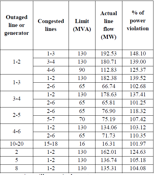
| Initially perform Newton Raphson load flow analysis to determine whether the limit is violated or not. If the limit is violated congestion will occur. From the load flow analysis results it was found that there is no congestion in test system. Next N-1 contingency analysis is carried out to find the critical outage cases are shown in Table I.From the analysis it is found that outage of lines such as 1-2, 1- 3, 3-4, 2-5, 4-6, 10-20 and outage of generators 2, 5, 8 have resulted in overload on other lines.In this study all the above said line and generator outage cases are considered. Nine test cases are considered for simulation as follows. |
 |
| To carry out the critical contingency ranking in the system, the PI values as defined in Eq. (1) are computed for each of the generators and line outage cases in the system. The PI values formost critical outages with the peak loading, in order of relativeseverity (descending order of the PI values) are given in Table II. It can be observed from Table II, the outage of line 1-2 inthe system gives rise to the most critical contingency condition. By taking the most critical case (i.e. line 1–2), |
 |
| congestion will occur in the system. |
| The congested linesare 1-3, 3-4 and 4-6 which are overloadedwith 148.103%, 139.008% and 125.371%, respectively. Thus, to relieve this transmission congestion, suitable control actions must be taken, which can be controlled by using the method associated with power flow control. In order to achieve this, the first and foremost method is to reschedule the generators. But in this work, corrective action for relieving congestion has been taken at the load buses by placing the DG at suitable locations. |
 |
| To find the suitable location of DGs, the sensitivity based LFSF have been calculated for each of the overloaded lines for the mostcritical contingency, which are listed in Table III. Only five suitable locations for each of the overloaded lines, in descending order of values, are shown in this table. |
 |
| It can be observed that bus-22 and bus-23 having the highest negative value, is the most suitable location for the DG placement with respect tothe overloaded lines 1-3, 3-4, 4-6 respectively. |
 |
| After placing all the DGs at their suitable locations, having optimal capacity it has been observed that the congested lines 1-3, 3-4 and 4-6 becomes relieved of 3.9806%, 9.5926% and 15.9254% respectively with critical contingency condition. While for system intact case with the placement of DGs the line flow in these lines become 38.70%, 35.90%, and 34.23% respectively. |
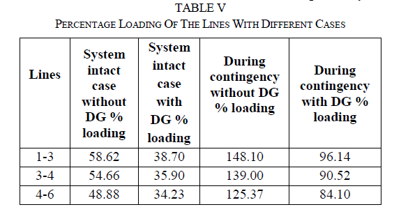 |
| The comparative analysis of the line flows under various cases with and without DG placement are shown in Table V. |
| Table VI, shows the real and reactive power losses before and after placing the DGs. |
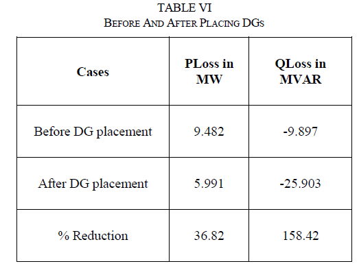 |
| It is evident from the table VI there is a reduction in losses to an appreciable amount, i.e. reduction of real power loss is 36.82% and reactive power loss is 158.42%. |
IV. CONCLUSION |
| In this paper, congestion management is done by optimum placement of DG in the distribution network. As it is known that non-optimal size and non-optimal placement of DG units may lead to high power loss and bad voltage profiles, therefore, in this paper Line Flow Sensitivity Factor (LFSF) analysis is utilised to determine the optimal location of DG units, as well as Genetic Algorithm (GA) for determining the optimal size of DG in distribution system to minimize the system loss and voltage deviation. The effectiveness of thismethod is tested on IEEE-30 bus system. This method of congestion relief by GA is computationally efficient and simple as it utilizes the sensitivity factors, which can be easily implemented for future expansion of the system and also for planning and operation of system economically. |
References |
|