ISSN ONLINE(2319-8753)PRINT(2347-6710)
ISSN ONLINE(2319-8753)PRINT(2347-6710)
| Snekapriya T, Vithya.T |
| Related article at Pubmed, Scholar Google |
Visit for more related articles at International Journal of Innovative Research in Science, Engineering and Technology
Photovoltaic power generation is one of the major factor key to resolve energy demand. The proposed method is used to solve the string converter connection problem in photovoltaic (PV) power generation system, using non-dissipative string current diverter. The power generated by each PV module and the output voltage become unbalanced under inhomogeneous irradiation. A non-dissipative string current diverter is used to overcome this problem. String current diverter circuit is very easy to control and does not operate without inhomogeneous irradiation. Maximum power point tracking technique (MPPT) implemented in PV system to maximize the PV module output power where the latter depends on solar irradiance and temperature. Maximum power point tracking algorithm implemented on each dc-dc converter and to do so at the optimum efficiency.
Index terms |
| string converter, zeta converter, MPPT and non-dissipative current diverter. |
INTRODUCTION |
| The availability of conventional sources of energy is decreasing, while the demand of energy in the world is increasing. Among this, there is a major impact towards environmental pollution and also will create to unwanted effects. Due to these reasons, renewable energy sources are being explored towards to meet the supply of energy in the world. There are some non-conventional sources of energy like tidal energy, wind energy, geo thermal energy etc. the solar –PV system has many advantages like it has no moving parts, less maintenance, easy availability of solar fuel, is pollution Free, and has a long life [1]. Series of connected photovoltaic module was used to create high voltages. However, in real conditions the performance of this photovoltaic module is negatively affected if all its modules are present in the PV cell is not equally illuminated. In partial shading conditions the PV modules are produced less photo current. The shaded modules will get opposite biased, then it will act as a load and dissipating power from fully illuminated modules in the form of heat, if the PV module is not appropriately protected, hot-spot problem will arise, the system can be irreversibly damaged. [2], [3]. String circuit is used to reduce the influence of partial shadow to some extent, they could not solve the maximum power point tracking (MPPT) problem in the shaded string circuit because the presence of PV module has multiple power peaks due to the existing MPPT schemes which are unable to discriminate between the local and global power peaks. [4].Walker and Sarnia (2004) have proposed topology non-isolated per panel dc-dc converters connected in series to create high voltage string. Justified that buck suited for long strings, boost converter for short strings, in order to improves the efficiency [5]. To mitigate the string converter problem the Module Integrated Converter (MIC) was introduced. This paper also discussed about the modeling of the zeta converter. In the present paper, string converter connected with non-dissipative string current diverter is proposed to balance the output voltage. The nondissipative current diverter independently used to balance the output voltage under inhomogeneous illumination condition. The simulation studies are performed using MATLAB/Simulink software to validate the efficiency of the string converter scheme at different irradiation conditions. |
II. PHOTOVOLTAIC MODULE |
| A PV cell is an electronic device used to convert sunlight into electricity. PV cell made up of PN junction. When the sunlight falls on the cell, the photons are generated by the semiconductor. From the negative layer freeing electron finds its path through an external circuit towards the positive layer so that electric current is generated [6]. Light falls on the PV cell produces both current and voltage, if sunlight falls on the one meter square areas of PV cell produce 1 to 2 watts of power. Two factors are important for generating power in the PV module that is irradiance and temperature. The PV cells are connected in series and/or parallel to form a PV panel. If the PV cells connected on series their voltages are added. Fig. 1 shows the equivalent circuit of the PV cell. That consists of a current source and parallel with the diode under constant temperature and irradiance conditions, the output of the PV module power is constant. |
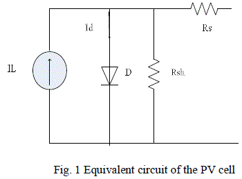 |
| The photon generated current will equal to the short circuit current of the PV cell, Iph=Isc By applying, the Kirchoff’s current law (KCL) on the equivalent circuit. |
 |
| Where, Isc is the short circuit current Id current shunted through the diode (v) Rp is the parallel resistance (ohm) Id is given by the Shockley’s diode equation By applying KVL on the equivalent circuit |
 |
| Where: V is the voltage across the PV cell I is the output current from the cell |
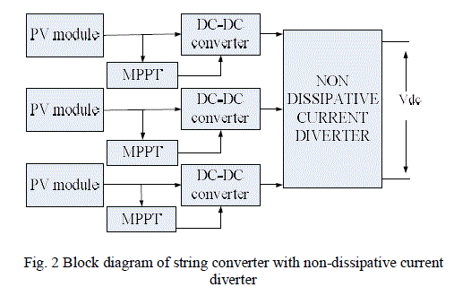
| BP Solar BP SX 150S PV module is chosen for a MATLAB simulation model. The module is made of 72 multi-crystalline silicon solar cells in series and provides 150W of nominal maximum power.Electrical specification for BPSX 150W solar module (Go = 1KW/m2, 25 C) is shown in Table 1. |
 |
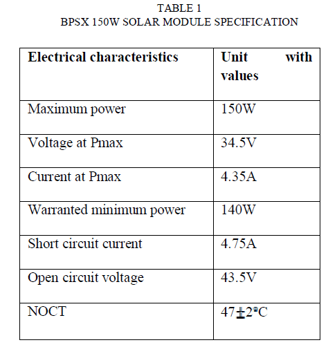 |
| Fig. 2 shows the block diagram of proposed string converter with non-dissipative current diverter. To balance the output voltage under inhomogeneous irradiation condition non dissipative current diverter is used to overcome this problem. Non dissipative current diverter is used to divert the output currents of dc-dc converter away from the unshaded PV module to the next module in the string. |
III. ZETA CONVERTER |
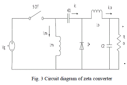
| Zeta converter is a type of DC-DC (Direct Current to Direct Current) converter. That allows the electrical potential at the output side. Zeta converter output will be greater than, less than or equal to that at its input. A zeta converter similar to a conventional buck boost and cuk converter, but zeta converter has the advantages of having non-inverted buck boost converter function. It has an input inductor and a capacitor as energy transfer devices |
 |
 |
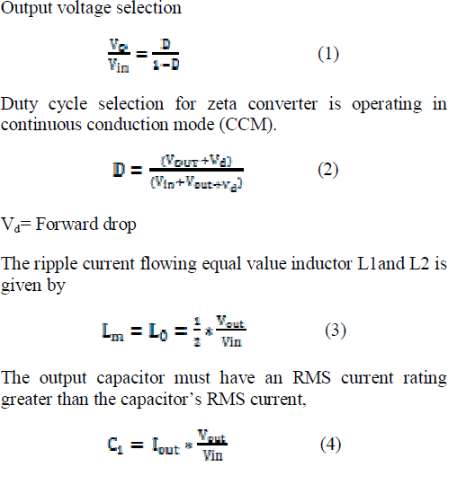
| Fig. 3 shows the circuit diagram of the zeta converter. The amount of energy exchanged is controlled by switch is typically a transistor such as a MOSFET and IGBT, it much higher input impedance and lower voltage drop than bipolar junction transistors (BJTs).the zeta converter can be operated in continuous and discontinuous mode based on the current flow in the inductor. A. Continuos conduction Mode (CCM) |
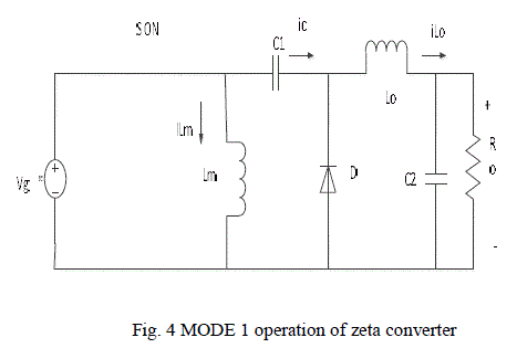
| Zeta converter is said to be in continuous conduction mode, if the current through the inductor Lm never falls to zero. When the switch is closed and the diode D is OFF. Fig. 4 shows the MODE 1 operation of zeta converter. During this period, the current through the inductor Lm and LO are drawn from the voltage source vg .in this mode is the charging mode. |
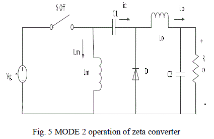 |
| Fig. 5 shows the MODE 2 operation of zeta converter. When the switch is OFF and the diode is ON. In this mode known as a discharging mode since energy stored in the Lo is now transferred to the load [7]. |
 |
IV. MAXIMUM POWER POINT TRACKING (MPPT) |
| Maximum power point tracking (MPPT) is an electronic system. That allows the modules to produce all the power they are capable of. Major focus is on the hill climbing, perturb and observe methods (P&O). Perturb and observe method involve perturbation in the duty ratio of the power converters, and P&O a perturbation in the operating voltage of the PV module connected to power converter, perturbing the duty ratio of the power converter perturbs the PV module current and consequently perturbs the PV module voltage [8]. In this algorithm a slight perturbation is introduced. Due to the perturbation the power of the module will be changes. If the power increases due to the perturbation then the perturbation then the perturbation is continued in that direction. After the peak power is reached the power at the next instant decreases and hence after that the perturbation reverses. When the steady state is reached the algorithm oscillates around the peak point. In order to keep the power variation small the perturbation size is kept very small. The flowchart of the algorithm is shown Fig. 6. |
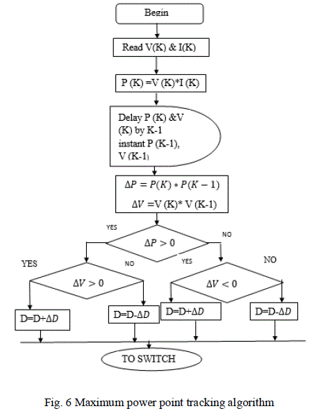 |
| The algorithm reads the value of current and voltage from the solar PV module. Power is calculated from the measured voltage and current. The value of voltage and power at Kth instant are stored. Then next values at (K+1)th instant are measured again and power is calculated. The power and voltage at (k+1)th instant. If the observe the power voltage curve of the PV module in the right hand side curve where the voltage is almost constant the slope of power voltage is negative dp/dv<0 where as in the left hand side the slope is positive dp/dv>0. The right side curve is for the lower duty cycle, whereas in the left side curve is for the higher duty cycle [9]. |
V. NON DISSIPATIVE CURRENT DIVERTER (NDCD) |
| Non dissipative current diverter helps to divert the output current of the converter away from the unshaded PV module to the next module in the string. And also allows the shaded modules to be operating at the maximum power point voltage. In this case consider only three PV modules. Each diverter module consist of a switch pair (MOSFETs) in the addition to an energy storage element L. during normal climatic conditions, the diverter modules are disabled and gives the output through the converter. When one or more PV modules are shaded, the corresponding current diverter is enabled to divert the string current. For N number of PV modules, the number of active switches N (MOSFET and diode D) is 2N-1 while the number of inductive shunts is N-1. During operating condition, the diverter circuit provides equalization output by directing energy from unshaded PV converter to the shaded PV converter. Operating duty cycle ratio is 50%. |
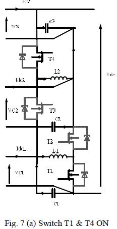
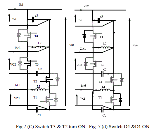
| [A].Modes of operation of NDCD Our project aims is to keep the voltage at the constant during inhomogeneous irradiation condition. If the PV2 module is shaded, the current drawn by the diverter (IL2, IDi) are presented first; the MOSFET T4 is turned ON Fig.7 (a).as a result, the inductor current IL2 increases linearly and the energy stored in the inductor L2. When the switch is turned OFF, the energy stored in the inductor delivered to the output capacitor of the dc-dc converter connected to the shaded module (in this case PV2 module) is shown in Fig.7 (b). As a result, the inductor current ramps down in a linear fashion. If the energy stored in the inductor L2 is completely transferred to capacitor C2 and the MOSFET T3 is always turn on and the current IL2changes their direction is shown in Fig.7(c), when the MOSFET T4 is turned on. |
| The diode D4 transfer the energy stored in the inductor L2 to the capacitor C3 Fig.7 (d) [10]. |
 |
 |
VI. SIMULATION RESULTS |
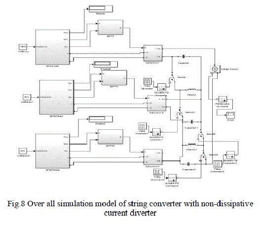
| In this section, deals with the simulation model for string converter with corresponding non dissipative current diverter. The PV module is simulated using MATLAB/Simulink. A mathematical computation tools are computer programs that combine computation and visualization power that make them particularly useful tools for engineers. MATLAB is both a computer programming language and software environment for using that language effectively. |
 |
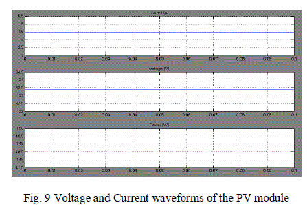
| Solar module was connected with blocks such as current sensor and voltage sensor to measure the current and voltage across solar module. The voltage and current waveform is shown in Fig. 9 for BPSX 150W based on under standard irradiance condition. |
 |
| The zeta converter (dc-dc converter) is simulated using MATLAB/Simulink. The storage devices inductor and capacitor is connected in the converter. Based on the duty cycle, the converter operates in buck and boost mode of the converter. Fig 10 shows the output waveform for buck and boost operation of zeta converter. |
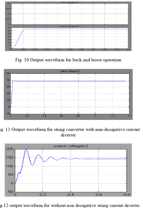 |
| The result shows in Fig.11, is that the proposed balanced output voltage with corresponding non dissipative string current diverter. Unbalanced output voltage is shown in Fig.12 without non-dissipative string current diverter. |
VII. CONCLUSION |
| In order to improve the performance of string converters topology under shading conditions, the proposed non-dissipative string current diverters connected to each converter. During normal climatic conditions, the diverter modules are disabled and the string current flows serially through all output capacitor of each converter. When one or more PV modules are shaded, the corresponding current diverter is enabled to divert the string current. The nondissipative current diverter also used to balance the output voltage from the photo voltaic module under partial shading conditions. Moreover, the presented topology allows to effectively applying the algorithms of MPPT under shaded conditions. The simulation and proposed topology exhibits good performance under inhomogeneous and homogeneous irradiations. |
References |
|