International Journal of Innovative Research in Science, Engineering and Technology
ISSN ONLINE(2319-8753)PRINT(2347-6710)
ISSN ONLINE(2319-8753)PRINT(2347-6710)
R. Balachandar1, S. Vinoth kumar2, C. Vignesh3
|
| Related article at Pubmed, Scholar Google |
Visit for more related articles at International Journal of Innovative Research in Science, Engineering and Technology
This paper presents a speed sensorless with direct torque control scheme using space vector modulation (DTC-SVM) for permanent magnet synchronous motor (PMSM) drive based a Model Reference Adaptive System (MRAS) algorithm. The MRAS is utilized to estimate speed and reduced the torque ripple & improves the accurate output. In other hand the use of SVM method reduces the torque ripple while achieving a good dynamic response. Simulation results are presented and show the effectiveness of the proposed method.
Index Terms |
| Model Reference Adaptive System (MRAS), permanent magnet synchronous machine (PMSM), space vector modulation (SVM), direct torque control (DTC), Sensorless drive. |
INTRODUCTION |
| PERMANENT magnet synchronous motors have (PMSM) been widely used as servo machines last two decades. The control methods used for the permanent magnet synchronous motors are: V/f control, field oriented control and direct torque control [1]. Stator coils placed on the stator are three phase and the amount of current drawn from the supply is minimal that leads to low losses of the rotor and excitation, increase of efficiency comparable with other motors and savings on energy costs. Radial rotor based motors have high cost because of this motors used in high technology. These motors are usually known as interior permanent magnet synchronous motor (IPMSM). Many techniques have been proposed in order to estimate the rotor speed and position, such as open -loop estimators using stator voltages and currents, back EMF-based position estimators, MRAS estimators, observe-based position speed and position estimators, high-frequency signal injection and artificial intelligence. For using mechanical position sensor could be bulky. In that sensor are easy to failure in harsh environments. The basic principle of DTC is to directly select stator voltage vectors according to the differences between the reference and actual torque and stator flux linkage. The DTC possesses advantages such as lesser parameter dependence, fast torque response when compared with the torque control with PWM current control [2]. The Method of observers is sometimes more favourable due to its robustness to parameter variations and its excellent disturbance rejection capabilities. Adaptive or robust observers based on advanced models [5]. his paper proposes the control strategy using space vector modulation (DTCSVM) based on the MRAS(Model Reference Adaptive System) in the sensorless speed control of a permanent magnet synchronous motor. It can overcome the problem of sensitivity in the face of motor parameter variation. |
II. PMSM MODEL |
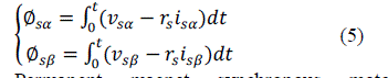
| The stator and rotor flux equation of PMSM can be written in the reference frame of Park in the following form: |
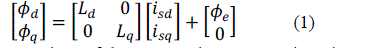 |
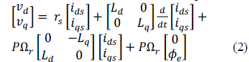
| While the equations of the stator voltages are written in this same reference frame in the following form: |
 |
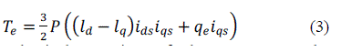
| In addition the electromagnetic torque can be expressed: |
 |
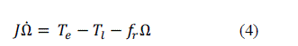
| The mechanical equation of the motor can be expressed as flows: |
 |
III. CONVENTIONAL DTC |
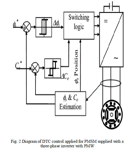
| DTC is a sensorless technique which operates the motor without requiring a shaft mounted mechanical sensor. It is suitable for control of the torque and flux without changing the motor parameters and load. In this method torque and stator flux are directly controlled by two hysteresis controllers. The block diagram of direct torque control for permanent magnet synchronous motor is shown in Fig. 1. |
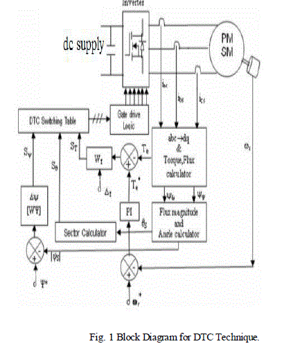 |
| The methods of direct torque control (DTC) consist of directly controlling the turn off or turn on of the inverter switches on calculated values of stator flux and torque from relation . The reference frame related to the stator makes it possible to estimate flux and the torque, and the position of flux stator. The aim of the switches control is to give the vector representing the stator flux the direction determined by the reference value. |
 |
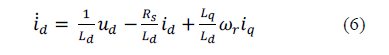
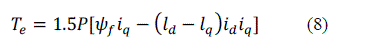
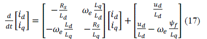
| Permanent magnet synchronous motor Equations Stator current vector on rotor flux (dq) reference system as id, iq and the electromagnetic torque is related with these vectors. Equations (6-7) and equation (8) are electrical and mechanical model equations respectively [3]. |
 |
 q q |
| Where rotor magnetic flux is is d axis stator inductance, is q axis stator inductance, is stator resistance, is electromagnetic torque, is load torque, is mechanical speed, is angular speed, J is moment of inertia, βis friction coefficient, p is number of pole couples. |
 |
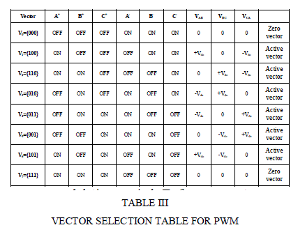
| A two levels classical voltage inverter can achieve seven separate positions in the phase corresponding to the eight sequences of the voltage inverter. |
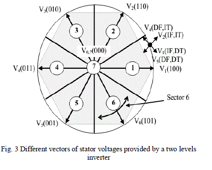 |
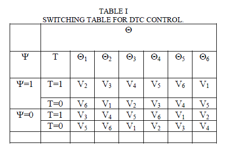
| Where: I (D)F : Increase (Decrease) of Flux amplitude. I (D)T : Increase (Decrease) of Torque. Table I have the sequences corresponding to the position of the stator flux vector in different sectors (see Figures 2). Voltage vectors controlling the amplitude of the stator flux, so the voltage vector plane is divided into six regions as shown in fig 3. In each region, there are two adjacent voltage vectors that increase or decrease the amplitude of ψs. For example, when ψs is in region 1, vectors of V1, V2, V6 and V3, V4, V5 are increase and decrease the amplitude of ψs, respectively. In this way, ψs can be controlled at the required value by selecting the proper voltage vectors [6]. Switching table, for controlling both the flux and torque are indicated in Table I. If ψ=1, and ψ=0 then the actual flux is smaller and bigger than the reference value, respectively. The same is true for the torque. |
 |
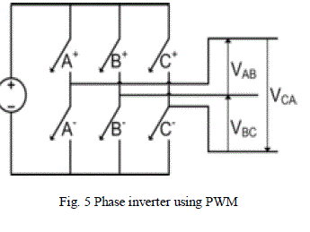
| Structure of voltage-source inverter (VSI) is shown in Fig. 5 at the same time only one switch on the each of column can be on [8]. |
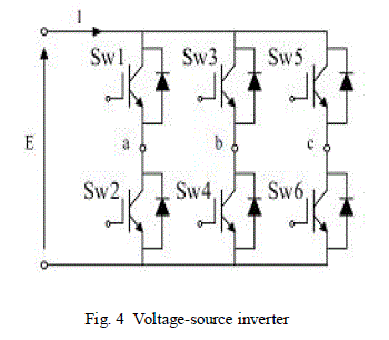 |
| By the different selects of the six switches, there are eight 41vectors that are six non-zero voltage vectors (V1, V2, V3, V4, V5, V6) and two zero voltage vectors (V7, V8) [2]. Line-to-line voltages are: |
 |
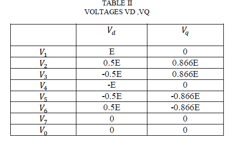
| The stator voltage-vectors (V1-V8) can be expressed in terms of the dc-link voltage (E) which obtained from transformation motor terminal voltages to stator D and Q axes. These voltages are show in Table II. |
 |
IV. SPACE VECTOR MODULATION |
| The Space Vector Modulation (SVM) is not based on separate calculations for each arm of a three-phase voltage inverter but by determination of a reference voltage vector from eight voltage vectors. This is generally calculated and approximated |
 |
| on a modulation period T from a vector average voltage developed by the application of adjacent voltage vectors and zero vectors V0 and V7. We note with Ti and Ti+1 a two-time application of these vectors; their sum must be less than the period T of the inverter switching. The SVM consists in projecting the reference voltage vector on both Vs ref desired voltage vectors V1 and V2 in the first sector and the application time of each adjacent vector. |
| A three phase inverter as shown to the right must be controlled so that at no time are both switches in the same leg turned on or else the DC supply would be shorted. This requirement may be met by the complementary operation of the switches within a leg. If A+ is on the A− is off and vice versa. This leads to eight possible switching vectors for the inverter, V0 through V7 with six active switching vectors and two zero vectors. |
| To implement space vector modulation a reference signal ïÿýïÿýïÿýïÿýïÿýïÿýïÿýïÿý is sampled with a frequency ïÿýïÿýïÿýïÿý (Ts = 1/fs). The reference signal may be generated from three separate phase references using the αβγ transform. The reference vector is then synthesized using a combination of the two adjacent active switching vectors and one or both of the zero vectors. Various strategies of selecting the order of the vectors and which zero vector(s) to use exist. Strategy selection will affect the harmonic content and the switching losses. |
 |
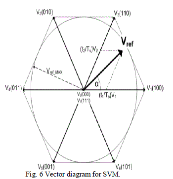 |
| All eight possible switching vectors for a three-leg inverter using space vector modulation. An example Vref is shown in the first sector. Vref-MAX is the maximum amplitude of Vref before non-linear over modulation is reached. |
V. MODEL REFERENCE ADAPTIVE SYSTEM |
| When the motor is running, its parameters will change and its performance will become bad. Adaptive control can remove this problem. The model reference adaptive system (MRAS) is an important adaptive controller [4]. The rotor speed is included in the (6) and (7) equations that present current model are relevant to rotor speed. So the stator current model is chosen as the state variable: |
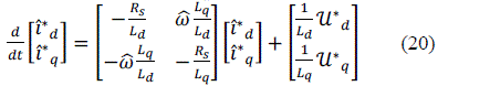 |
| Presume the adaptive mechanism as follow: |
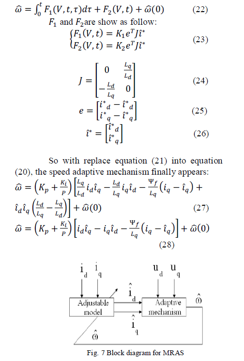 |
VI. SIMULATION OF SPEED SENSORLESS CONTROL OF PMSM BASED ON DTC METHOD WITH MRAS REFERENCE ADAPTIVE SYSTEM |
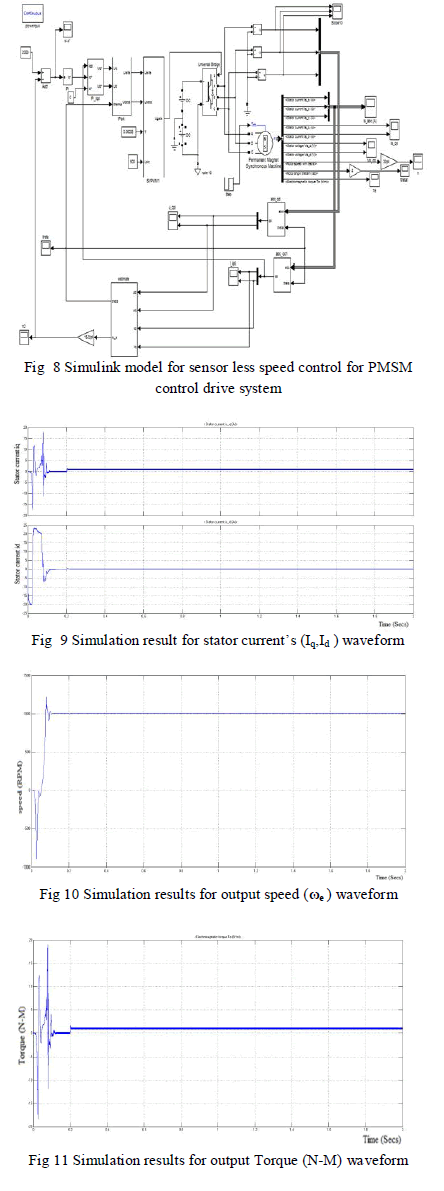
| In this proposed simulation diagram sensor less speed control for PMSM. In that system can be estimated the rotor speed and simulate with MATLAB software. Fig. 8 shows the block diagram of speed sensor less control of PMSM based on DTC method with adaptive system. In Fig. 8 the estimate output speed adaptive system of compare with the reference speed of input and uses from this speed as the real speed of machine.In that Fig 10 & 11 shows simulation results for speed and output torque for PMSM drives. |
 |
VII. CONCLUSION |
| In this MRAS technique is simple and it will reduce the mathematical computation time. The experimental results are obtained both in load torque and several speed conditions. Using the model reference adaptive system for estimate the rotor speed of a PMSM, it will effect of the variation of motor parameters. Experimental results have estimates the errors, it will global stability of the drive system for various operation condition. The proposed adaptive system is simulated by using MATLAB/ Simulink performance waveforms are verified. |
References |
|