ISSN ONLINE(2319-8753)PRINT(2347-6710)
ISSN ONLINE(2319-8753)PRINT(2347-6710)
Sivamurugan.R1, Dhayalini.K*2, Sathyamoorthy.S3
|
| Related article at Pubmed, Scholar Google |
Visit for more related articles at International Journal of Innovative Research in Science, Engineering and Technology
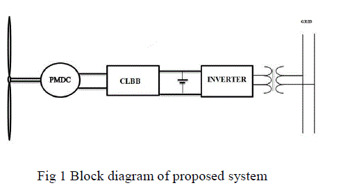
This paper presents a system in which a wind driven Permanent Magnet DC Generator (PMDC) feeds power to grid through a Buck-Boost converter. The output voltage of the PMDC is variable in nature due to non-uniform wind velocities. The fluctuating output is regulated and kept constant by means of a buck-boost converter. The buck-boost converter is provided with a closed loop feedback control, which is designed using a PID controller. In this converter, the output voltage is continuously sensed and duty ratio of the switch is varied to maintain a constant DC output voltage. This converter output is stored in a battery and converted to single phase ac using a diode clamped multilevel inverter. The power converters together with independent control systems can effectively improve the output voltage and frequency of the wind driven PMDC generator feeding power to grid. The proposed system is validated through 24V PMDC machine.
Keywords |
| PMDC generator, Closed loop Buck- Boost converter (CLBB), single phase diode clamped multilevel inverter |
INTRODUCTION |
| The demand for energy has increased tremendously in the past few decades. As a result, the use of renewable energy sources like solar energy, wind energy etc., is gaining popularity. Wind power has emerged as a viable and cost-effective option for power generation. Also studies shows that small-scale WECS are more efficient and cost effective. Wind turbine using PMDC is one of the most favorable and reliable methods of power generation. To meet the amplitude and frequency requirements of conventional loads as well as grid, the outputs of PMDC requires additional conditioning. This paper presents an efficient small scale wind energy conversion system using PMDC and power electronic converters. In the proposed system, the PMDC output is converted to constant DC using a Buck-Boost converter. This constant DC output is converted to AC using diode clamped multilevel inverter |
II.SYSTEM DESCRIPTION |
| The block diagram of the proposed system is shown in Fig. 1. |
 |
| A. Wind turbine model |
| wind turbine converts wind power into shaft power to drive an electrical generator or other load. In smaller electrical wind power systems the most common configuration is a 3-blade horizontal axis wind turbine coupled to the generator through the gear arrangement. The output power of the wind turbine is a function of wind velocity cubed [1][2]. It is described mathematically by equation (1) |
| where P is the power in Watts, CP is the dimensionless coefficient of performance, ρ is air density (kg/m3), A is rotor swept area (m2), and Vwind is the wind speed (m/s). |
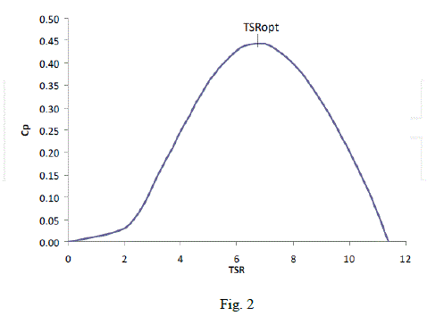
| The curve for coefficient of performance as a function of the tip speed ratio is shown in Fig 2. |
 |
| Wind speed below the âÃâ¬Ãâ¢cut in speedâÃâ¬Ãâ there is not enough wind power to overcome friction, thus no power is produced. Above the cut-in speed the power increases rapidly to the âÃâ¬Ãâ¢rated speed. Generally the turbine produces its rated power at the rated wind speed. The wind turbine torque is given by equation 2 |
 |
| ωr is the rotor speed. B. PMDC Generator PMDC generator is an electro-mechanical that converts the mechanical energy to electrical energy. The field of the PMDC is made up if permanent magnet, so there is no separate excitation is needed. So the losses associated with the field winding are avoided. The main advantage of using PMDC generator over AC generator is, less power conversion stages [2]. In AC generators the output is rectified and boosted up and converted to AC. Whereas in DC generators it needs one regulator stage and inverter stage, so the efficiency is high. The dynamic equation of the PMDC generator is given by equation 3 |
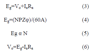 |
| Where Eg is the generated emf in the PMDC generator, Ra is the armature resistance Ia is armature current, N is the speed of rotation, Vo is the output voltage of PMDC generator. The disadvantage of using PMDC is, it is suitable for only low power applications. |
| C. Buck boost converter A Buck Boost Converter is a DC-DC regulator which provides an output voltage that may be less than or greater than the input voltage - hence the name âÃâ¬Ãâ¢Buck- BoostâÃâ¬Ãâ. As the polarity of the output voltage is opposite to that of the input voltage [3][4][5][6], the regulator is also known as an inverting regulator. The output voltage from the PMDC generator is variable in nature according to wind speed and it is regulated by using the CLBB. When the input voltage is low than the reference it act as the boost converter and when the input voltage is high than the reference voltage it act as the buck converter. The circuit diagram for the buck-boost converter is shown in fig.3. |
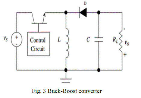 |
| The output voltage of the boost converter is given by, |
 |
| Where, Vs is the input voltage, Vout is the output voltage and α is the duty ratio of the switch. The CLBB boost or buck the variable DC input voltage to constant DC output voltage. In the proposed system a PI controller based CLBB is used. The output of the CLBB remains constant even if there is a variation in the input voltage. Closed loop is obtained by comparing the reference input with the output of buck boost converter. The duty ratio of the buck boost converter is adjusted to compensate the changes in input voltage and thereby keeps the output voltage at a desired value |
| D. Interfacing Inverter |
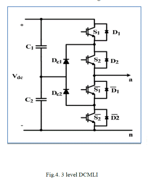
| An inverter is a circuit that converts DC to AC. PWM is a switching technique that is used to decrease the total harmonic distortion (THD) in the inverter circuit [7][8]. The output of CLBB is fed to a single phase three level diode clamped multilevel inverter which converts the constant DC to constant AC having a frequency of 50Hz. Inverter frequency is obtained from the grid. The schematic diagram of a single phase diode clamped multi level inverter is shown in Fig. 4. |
 |
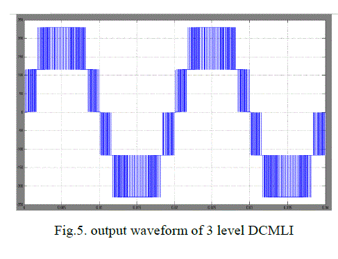 |
| where Vdc is the output of the CLBB, unipolar multi career SPWM switching is employed. This makes the filtering easier. Three level diode clamped multilevel inverter requires (m-1) capacitors and 2(m-1) switching devices per leg and (m-1)(m-2) clamping diodes per leg. The advantage of using multilevel inverter over H bridge inverter is having reduced harmonics and it can be easily filtered out.Waveform of the three level diode clamped multi level inverter is shown in fig.5. |
III. CONTROL SYSTEM |
| The control system of the proposed system includes control of the CLBB and the interfacing inverter. Control of the buck-boost converter aims in maintaining a constant DC input to the interfacing inverter. Control of interfacing inverter provides frequency control. |
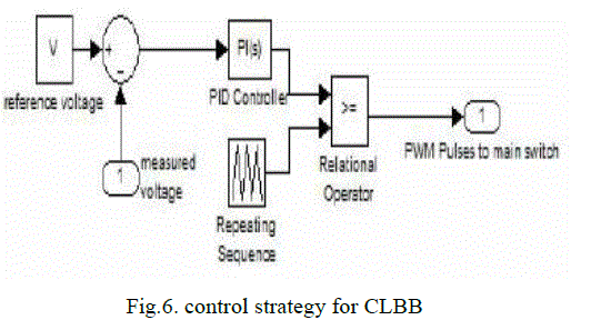
| A. Control strategy for CLBB Control strategy for closed loop DC-DC buck-boost converter is shown in Fig. 6. Here the output voltage is sensed and it is compared with a set reference voltage [10]. The error is processed through a PID controller. The output of PID controller is used to modulate the pulses that drive the MOSFET gate. The gate signals of MOSFET are generated by PWM by comparing a carrier signal with the signal generated by PID controller. The simplest way to generate a PWM signal is the interceptive method, which requires only a saw tooth or a triangle waveform and a comparator. |
 |
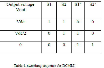
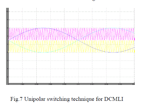
| B. Control strategy for interfacing inverter Control strategy for grid side inverter is shown in fig.6. In order to connect the inverter to the grid one of the condition necessary to be satisfied is the frequency matching. Frequency matching is achieved by taking the grid frequency as the reference for inverter operation. PWM switching technique is used, in which the sine wave and its inverted wave is compared with the carrier signal is shown in figure.7. The gate pulses are given to the switches through the driver circuit. The switching sequence for DCMLI is shown in table 1 |
 |
 |
IV. SIMULATION RESULTS |
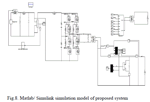
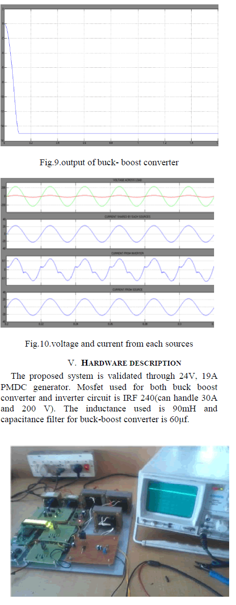
| The proposed model is simulated using MATLAB7.1 and the simulation model is shown in Fig. 8. The voltage is measured at different points in the simulation circuit. The PMDC generates variable DC voltage. The generated output is converted to regulate DC with the closed loop buck-boost converter (CLBB). Thus the output at the CLBB is always rated voltage as shown in Fig 9. The output of the CLBB is constant at 15V DC. CLBB parameters are L=90 mH, C= 60 mF, fs=10 kHz, V0=15V, Kp= 0.029, Ki =.55 and transformer rating 12/230. The output of the CLBB is then converted to single phase AC using three level diode clamped multilevel inverter. The power generated is feed to the grid. |
 |
| Fig.9 shows the output of the buck boost converter. Fig.10 shows the voltage across the load and current through the load and current drawn from grid and inverter circuit. |
 |
VI. CONCLUSION |
| This paper presents the efficient control method for PMDC based wind energy conversion system. In the proposed system the output of the PMDC is converted to constant voltage using CLBB with PID controller. This voltage is converted to AC using diode clamped multilevel inverter and fed in to grid through step up transformer. With the proposed method wind energy is effectively used there by partly reducing the power demand. And also it helps in pollution free environment |
References |
|