ISSN ONLINE(2319-8753)PRINT(2347-6710)
ISSN ONLINE(2319-8753)PRINT(2347-6710)
Vignesh T.1, Hemnath B.G.1, Chinagounder c1, Sutharsan P1., Caesar J.2
|
| Related article at Pubmed, Scholar Google |
Visit for more related articles at International Journal of Innovative Research in Science, Engineering and Technology
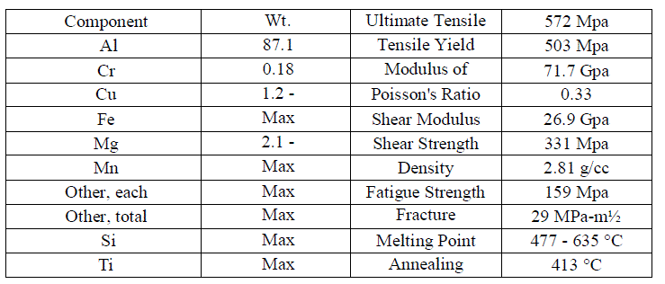
Recent survey concludes that fatigue failure results in many fatal accidents to the aircrafts. So in order to reduce fatigue failure, static stress and fatigue analysis have been done for vertical stabilizer of a typical trainer aircraft at +4g factor condition. Design modeling of component is done using CATIA V5 software. Static stress analysis has been done using Patran and Nastran software. Aluminium 7075 T6 material which has high fatigue strength has been used in vertical stabilizer. From the static stress analysis, maximum principal stress value has been found out which is less than the yield strength of Al 7075 T6. The maximum principal stress value has been used in fatigue calculation and the obtained analytical result shows the safe number of factored fatigue life hours for the component. The result predicted in this work concludes the efficient number of factored fatigue life hours for the vertical stabilizer which would reduce the service cost of the component and ensures structural safety to the component
Keywords |
| Fatigue failure – fatal - static stress analysis - fatigue analysis -vertical stabilizer - +4g factor - CATIA V5 - Patran, Nastran - Al 7075 T6 - efficient-factored fatigue- life hours-service cost-structural safety. |
INTRODUCTION |
| Horizontal tail and vertical tail along with wing are referred to as lifting surfaces. This name differentiates tails and wing from control surfaces namely aileron, elevator, and rudder.[1] Due to this mane, several design parameters associated with tails and wing; such as airfoil, plan form area, and angle of attack; are similar. Thus, several tails parameters are discussed in brief. The major difference between wing design and tail design originates from the primary function of tail that is different from wing. Primary function of the wing to generate maximum amount of lift, while tail are supposed to use a fraction of its ability to generate lift.[2] If at any instance of a flight mission, tail nears its maximum angle of attack (i.e. tail stall angle); it indicates that there was a mistake in the tail design process. In some references, tail is referred to as empennage. Tail often in a conventional aircraft has two components of horizontal tail and vertical tail and carries two primary functions: Trim (longitudinal, lateral and directional) and Stability (longitudinal and directional) |
| Since two conventional control surfaces (i.e. elevator and rudder) are indeed parts of the tails to implement control, it is proper to add the following item as the third function of tails: Control (longitudinal and directional) |
II. FATIGUE FAILURE |
| Fatigue is the progressive and localized structural damage that occurs when a material is subjected to cyclic loading. [2]Fatigue occurs when a material is subjected to repeat loading and unloading. If the loads are above a certain threshold, microscopic cracks will begin to form at the surface. Eventually a crack will reach a critical size, and the structure will suddenly fracture. The shape of the structure will significantly affect the fatigue life; square holes or sharp corners will lead to elevated local stresses where fatigue cracks can initiate. Round holes and smooth transitions or fillets are therefore important to increase the fatigue strength of the structure. Metal fatigue is caused by repeated cycling of the load. It is a progressive localized damage due to fluctuating stresses and strains on the material.[4] Metal fatigue cracks initiate and propagate in regions where the strain is most severe. |
 |
 |
 |
IV. ANALYSIS |
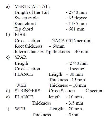
| Stress analysis is an engineering discipline that determines the stress in materials and structures subjected to static or dynamic forces or loads. A stress analysis is required for the study and design of structures, e.g., tunnels, dams, mechanical parts, aircraft component and structural frames among others, under prescribed or expected loads. Stress analysis may be applied as a design step to structures that do not yet exist. |
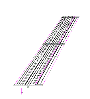
STEPS INVOLVED ANALYSIS USING NASTRAN PATRAN |
| 1) CAD Import |
| 2) Meshing of geometry |
| 3) Applying material properties |
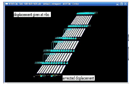
| 4) Loads and boundary conditions |
| 5) Load cases to analyze various sets of boundary conditions |
| 6) Analysis submission Analysis of results |
 |
COMPOSITION |
 |
 |
V. RESULTS |
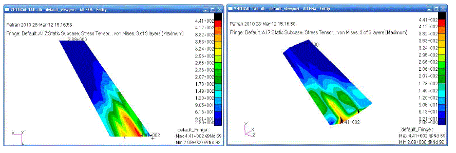
| From the linear static stress analysis, from the Nastran &Patran software, the von mises stress and the maximum principal stress for the vertical tail are obtained. Von mises stress and the maximum principal stress both acting at the bottom end of the leading edge spar. |
| Von mises stress: 441 Mpa |
| Maximum principal stress: 483 Mpa |
 |
 |
VI. FATIGUE |
| Fatigue is defined as the progressive deterioration of the strength of a material or structural component during service such that failure can occur at much lower stress levels than the ultimate stress level. Fatigue is a dynamic phenomenon which initiates small (micro) cracks in the material or component and causes them to grow into large (macro) cracks; these, if not detected, can result in catastrophic failure. |
 |
 |
 |
CONCLUSION |
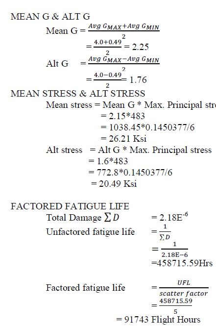
| The life hours have been calculated for vertical stabilizer from the fatigue analysis (stress- life method) and found to be 91743 Flight hours which is greater than the required life hours of range 60,000-80,000.Our result shows the efficient number of life hours. Within the life hours, the components do not need any service and maintenance and thus reduces the service and maintenance cost. This result shows the cost-effective factor for the component by using Aluminum 7075 T-6 material. From the Fatigue analysis it ensures the structural safety for the component within the calculated life hours |
VIII.FUTURE ENHANCEMENTS |
| The design of vertical tail has to be optimized for weight reduction. The local stress analysis has to be carried out for the structural members. The buckling analysis has to be done for the vertical tail to ensure that the skin buckles or not at the maximum load. |
References |
|