ISSN ONLINE(2319-8753)PRINT(2347-6710)
ISSN ONLINE(2319-8753)PRINT(2347-6710)
Ranjit M. Zende1, Suryakant H. Pawar2
|
| Related article at Pubmed, Scholar Google |
Visit for more related articles at International Journal of Innovative Research in Science, Engineering and Technology
Sub-synchronous resonance (SSR) is the process which leads to the turbine generator shaft damage. This work addresses Contributions of synchronous generator rotor motion and induction generation to sustained subsynchronous oscillation. The definitions regarding sub synchronous resonance phenomenon is presented. For analysis the IEEE second benchmark model system-1 is taken and discussed in detailed.
Keywords |
| Capacitor Compensated Transmission Lines, Sub-synchronous resonance, Induction Generator Effect, Torsional Interaction Effect, Transient Torque Effect |
INTRODUCTION |
| Series capacitor compensation has been widely used in the AC transmission systems [1] as an economical alternative for different purposes such as increasing power transfer capability through a particular interface, controlling load sharing among parallel lines, and enhances Steady state stability [2]. However, the use of series compensation may bring about some new problem to power system operation. One of the problems is possibility of Sub-Synchronous Resonance (SSR), which may lead to torsional oscillations of turbine generator shaft system and electrical oscillation with frequency below the sub synchronous frequency. Turbine-generator shaft failure and electrical instability at oscillation frequencies lower than the normal system frequency result from SSR. The two shaft failures at the Mohave Generating Station in Southern Nevada led to the advancements in understanding the SSR phenomenon as well as explaining the interaction between series capacitor compensated lines and the torsion mode of steam turbine-generators [3]. Turbine-generator electromechanical interaction with series capacitors has historically been known as the phenomena of "Sub synchronous Resonance" (SSR). The interactions between power controlling devices, such as HVDC converters, static var systems, and power system stabilizers, and turbine-generators has lead to a recognition of a broad range of' turbine-generator torsional interactions which is nothing but the sub synchronous oscillations. In this regard, this work presents a comprehensive approach towards SSR and IEEE second benchmark model. |
II. SUB-SYNCHRONOUS RESONANCE |
| Sub-Synchronous Resonance is an electrical power system condition where, electrical network exchanges energy with turbine generator at one or more natural frequency of combined system, below the synchronous frequency of the system [4]. The definition includes any system condition that provides the opportunity for an exchange of energy at a given sub synchronous frequency. This includes what might be considered "natural" modes of oscillation that are due to the inherent system characteristics, as well as "forced" modes of oscillation that are driven by a particular device or control system. The most common example of the natural mode of sub synchronous oscillation is due to networks that include series capacitor compensated transmission lines. These lines, with their series LC combinations, have natural frequencies n w and the condition for occurrence of SSR is given as below. |
III. NATURAL FREQUENCY |
 |
 |
| Where s is degree of series compensation “s” varies between 0 and 1 i.e. (0 < S <1) If S = 0, there is no series compensation. If s=1, we have 100% series compensation, the line has no reactance and only resistance predominates. Then power transfer, as with direct current, only by difference of voltage magnitudes, not by phase difference, and system is unstable. For s >1, the net circuit reactance is capacitive, and power curve is inverted. If 0 < s <1, then also 0 < s <1 and n f < s f There exit a risk of SSR. Where n ïÃÂ÷ is the natural frequency associated with a particular line LC product, s ïÃÂ÷ is the system base frequency, and XL and XC are the inductive and capacitive reactance’s respectively. These frequencies appear to the generator rotor as modulations of the base frequency, giving both sub synchronous and super synchronous rotor frequencies. It is the sub synchronous frequency that may interact with one of the natural torsional modes of the turbine-generator shaft, thereby setting up the conditions for an exchange of energy at a sub synchronous frequency, with possible torsional fatigue damage to the turbine-generator shaft. The torsional modes (frequencies) of shaft oscillation are usually known, or may be obtained from the turbine-generator manufacturer. The network frequencies depend on many factors, such as the amount of series capacitance in service and the network switching arrangement at a particular time. |
IV. TYPES OF SSR INTERACTION |
| There are many ways in which the system and the generator may interact with sub synchronous effects. A few of those interactions are basic in concept and have been given special names. We mention three of those that are of particular interest: Induction Generator Effect, Torsional Interaction Effect, and Transient Torque Effect [5]. |
A] INDUCTION GENERATOR EFFECT |
| Induction generator effect is caused by self excitation of the electrical system. The resistance of the rotor to sub synchronous current, viewed from the armature terminals, is a negative resistance. The network also presents a resistance to these same currents that is positive. However, if the negative resistance of the generator is greater in magnitude than the positive resistance of the network at the system natural frequencies, there will be sustained sub synchronous currents. This is the condition known as the "induction generator effect." |
B] TORSIONAL INTERACTION |
| Torsional interaction occurs when the induced sub synchronous torque in the generator is close to one of the torsional natural modes of the turbine generator shaft. When this happens, generator rotor oscillations will build up and this motion will induce armature voltage components at both sub synchronous and super synchronous frequencies. Moreover, the induced sub synchronous frequency voltage is phased to sustain the sub synchronous torque. If this torque equals or exceeds the inherent mechanical damping of the rotating system, the system will become self excited. This phenomenon is called "torsional interaction." |
C] TRANSIENT TORQUES |
| Transient torques is those that result from system disturbances. System disturbances cause sudden changes in the network, resulting in sudden changes in currents that will tend to oscillate at the natural frequencies of the network. In a transmission system without series capacitors, these transients are always dc transients, which decay to zero with a time constant that depends on the ratio of inductance to resistance. For networks that contain series capacitors, the transient currents will be of a form similar to above equation, and will contain one or more oscillatory frequencies that depend on the network capacitance as well as the inductance and resistance. In a simple radial R-L-C system, there will be only one such natural frequency, which is exactly the situation described in above equation , but in a network with many series capacitors there will be many such Sub synchronous frequencies. If any of these sub synchronous network frequencies coincide with one of the natural modes of a turbine-generator shaft, there can be peak torques that are quite large since these torques are directly proportional to the magnitude of the oscillating current. Currents due to short circuits, therefore, can produce very large shaft torques both when the fault is applied and also when it is cleared. In a real power system there may be many different sub synchronous frequencies involved and the analysis is quite complex. Of the three different types of interactions described above, the first two may be considered as small disturbance conditions, at least initially. The third type is definitely not a small disturbance and nonlinearities of the system also enter into the analysis. From the view point of system analysis, it is important to note that the induction generator and torsional interaction effects may be analyzed using linear models, suggesting that Eigen value analysis is appropriate for the study of these problems. |
V. ELECTRICAL NETWORK PRESENTATION |
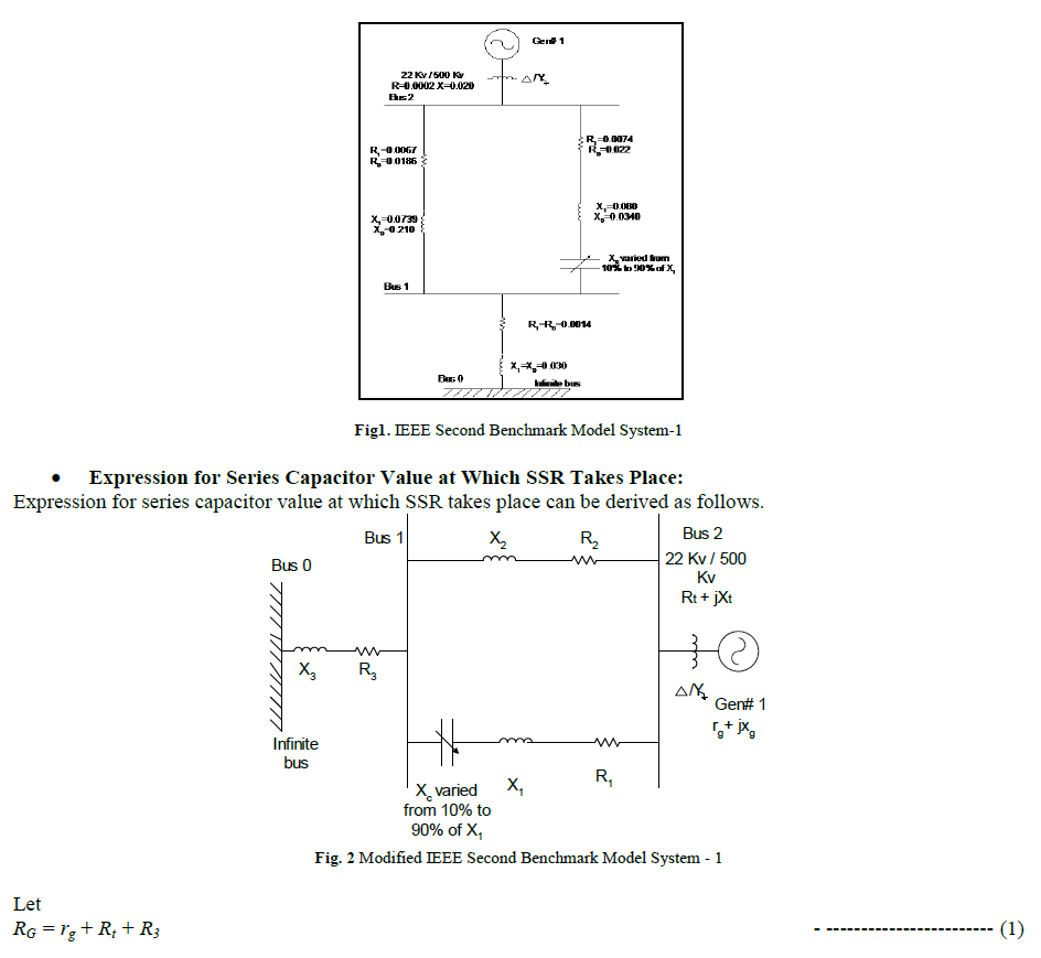
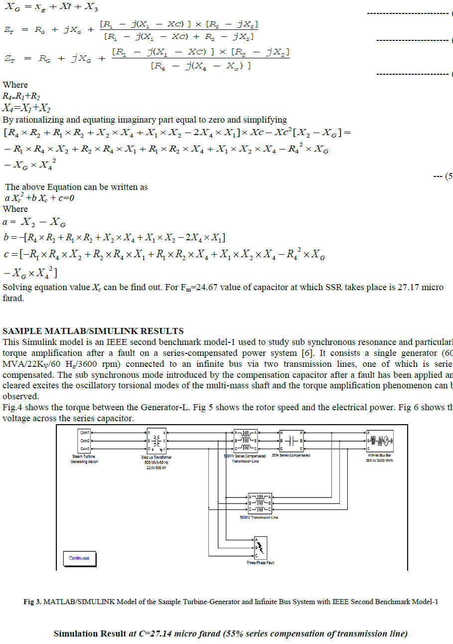
| Electrical Model for Analysis of SSR: Here IEEE Second Benchmark model is given for the Analysis of SSR, which deals with so-called parallel resonance [6]. One line diagram of IEEE second benchmark model is shown in below figure 1. The electrical modal of the studies system comprises the GEN connected to an infinite bus through step up transformer and two parallel transmission lines, one of which is series compensated. The value of XC/XL of the compensated line in fig. defines the series compensation ratio. The capacitive reactance XC can be varied and XC/XL is ranged from 10% to 90%. The mechanical system comprises four masses, i.e. the HP, LP, GEN, and EXC, which are mechanically coupled on the same shaft. From the structure of this model mass spring system, there exists three torsional modes (mode 1, mode 2, and mode 3) and one electromagnetic mode (mode 0) in the system. These four-modes are called SSR modes or torsional modes since there natural frequencies are all less than synchronous frequency or power frequency (60Hz). The inherent natural frequencies for mode 0, 1, 2 and 3 are 1.35Hz, 24.17 Hz, 32.39Hz and 51.12 Hz, respectively. The SSR mode i (i= 0, 1, 2, 3) stands for the number of twists on the shaft. For example mode 0 signifies the four masses oscillate in unison without a shaft twist, mode 1has one shaft twist , mode 2 has two shaft twists, etc so on. All turbine torques proportional, with each contributing fraction. The fractions for both HP and LP are 70% and 30% respectively. |
 |
 |
 |
VI. CONCLUSION |
| The proposed work presented a comprehensive approach for sub-synchronous resonance (SSR). Thus with the help of IEEE Second Benchmark Model we can analyze the Sub Synchronous Resonance (SSR) Phenomenon. The main cause of the Production of SSR is the Series Compensation. There are other sources responsible for excitation of SSR are Power System Stabilizer (PSS), HVDC Convertor, Static Var Compensator (SVC), Variable Speed Drive Convertor. Models have been prepared for turbine-generators and systems to compare self-excitation and torque amplification analytic techniques. The systems have only been made complex enough to provide for "parallel resonance" and interaction between turbine-generators having torsional modes. |
References |
|