ISSN ONLINE(2319-8753)PRINT(2347-6710)
ISSN ONLINE(2319-8753)PRINT(2347-6710)
Dr. B. S. Gawali1, V. B. Swami2, S. D. Thakre3
|
| Related article at Pubmed, Scholar Google |
Visit for more related articles at International Journal of Innovative Research in Science, Engineering and Technology
Investigation of heat transfer characteristics has been carried out by theoretically and experimentally for a straight microchannel heat sink of rectangular cross section of 507μm hydraulic diameter with water as the circulating fluid. The temperature distribution, pressure drop, heat transfer coefficient and total thermal resistance of the heat sink are selected as criteria for their cooling performance. Parameters that changes in this study are Reynolds number in ranges from 200 to 700. The theoretical results for heat transfer coefficient and thermal resistance are compared with the experimental results. The obtained theoretical results are having the good agreement with experimental results. It is found that the temperature of water in the microchannels increases with channel length. The present work proposes an approach to improve the heat transfer enhancement of microchannel heat sinks
Keywords |
| Microchannel Heat Sink, Hydraulic diameter, Aspect ratio, Pressure drop, Heat Transfer Coefficient. |
I. INTRODUCTION |
| Microchannels have become very popular in applications where very high heat transfer rates are necessary. It's development trend as electronics equipment becomes more advanced and smaller in size with continuing innovations. It faces thermal engineering challenges from the high level of heat generation and the reduction of available surface area for heat removal. In the absence of sufficient heat removal, the working temperature of this component may exceed a desired temperature level which then increases the critical failure rate of equipment. Therefore, advanced electronic equipment with high heat generation requires an efficient and compact device to provide proper cooling operation [1]. In order to meet the cooling requirement, needs to increase the product of heat transfer coefficient (h) and heat transfer surface area (A) for a device. Since heat transfer coefficient is related to the channel hydraulic diameter [2]. The heat transfer surface area can be increased by incorporating micro channels on the device surface. |
| One promising solution to the problem is liquid cooling incorporating on microchannels [3]. Microchannel heat transfer has the potential of cooling high power density microchips. One can expect that as the size of the channel decrease, the value of convective heat transfer coefficient(h) becomes increasing in order to maintain a constant value of the Nusselt number (hDh/kf). These chips have machined microchannels through which cooling fluid like water is circulated. The cooling liquid removes heat by single phase forced convection. Flow within the microchannel is considered as fully developed laminar flow with constant heat flux. Therefore, heat sinks with larger extended surfaces, highly conductive materials and more coolant flow are key parameters to reduce the base temperature [4]. For intermediate heat fluxes, single-phase cooling offers an alternative that is simpler to implement and thus preferable [5]. |
| The work in this paper is divided in two stages. 1) Theoretical investigation 2) Experimental investigation. Theoretical investigation is done by applying formulae which is given by S. G. Kandlikar et al. [6]. Heat transfer and fluid flow in minichannels and microchannels book. Thereafter, constant heat flux at bottom of channel and other three walls adiabatic consider as a boundary conditions for an investigation of microchannels. |
| Paper is organized as follows. Section II describes related work [Literature Survey], Section III describes analysis of microchannel heat sink using theoretical investigation, studied classification of channels. Analysis of microchannel heat sink using experimental investigation that is given in Section IV. Section V presents theoretical and experimental results. Finally, Section VI presents conclusion. |
II. RELATED WORK |
| Tuckerman and Pease [1] first suggested the use of microchannels for high heat flux removal, which employed the direct circulation of water under laminar condition through microchannels heat sinks fabricated in silicon wafer. This heat sink is simply a substrate with numerous small channels and fins are arranged in parallel, such that heat is efficiently carried from substrate to coolant. They managed to produce large aspect ratio heat sink with channel width in the order of 50 μm. Heat flux as high as 790 W/cm² was achieved with the chip temperature maintained below 110 ºC. I. Hassan et al. [2] gives the information about microchannel, which is used in computers for cooling of high powered ICs. The heat generated by the electronic component is transferred to the coolant by forced convection. Laminar flow is the best for heat removal through microchannels, due to the development of the thin thermal boundary layer. C. B. Sobhan and S.V. Garimella [3] indicate that before predictions of flow and heat transfer rates in microchannels can be made with confidence, careful experiments are needed to resolve the discrepancies in the literature and to provide practical information on the design of microchannel heat sinks. S.G. Kandlikar and W.J. Grande [4] give the information about heat removal from the high heat flux devices also gives flow boiling concept for high heat flux cooling application in minichannel and microchannels. Flow boiling is superior to single-phase liquid cooling from two main considerations-namely a high heat-transfer coefficient during flow boiling and higher heat removal capability for a given mass-flow rate of the coolant. Poh-Seng Lee et al. [5] discuss experimental results of rectangular microchannel, consider a microchannels width from 194 μm to 534 μm, with the channel depth being nominally five times the width in each case. Each test piece was made of copper and contained ten microchannels in parallel. The experiments were conducted with deionized water, with the Reynolds number ranging from approximately 300 to 3500. Also numerical approach is compared with the experimental one and found to be in good agreement. Lee and Garimella [7] performed three dimensional numerical simulations for laminar thermally developing flow in the entrance region of microchannels of rectangular cross section of different aspects ratios under circumferentially uniform wall temperature and axially uniform heat flux thermal boundary conditions. They were proposed generalized correlations for predicting Nusselt numbers useful for the design and optimization of microchannel heat sinks. The proposed correlations were compared with conventional correlations and with available experimental data, and show very good agreement. Shah and London [8] gives information about boundary layer developed conditions, thermally and hydrodynamically entry length effects. Shekhar D. Thakre and V. B. Swami [10] discuss analysis of heat transfer characteristics through a straight and wavy profile rectangular microchannel heat sink with Reynolds number from 100 to 1000 and same effective length. |
III. THEORETICAL INVESTIGATION |
| The rate of the heat transfer process depends on the surface area, which varies with the hydraulic diameter of a microchannel where as the flow rate depends on the cross-sectional area, which varies linearly with Dh 2. Kandlikar and Grande 2004 [4], classified the channels based on their smallest dimension, Dh, On the basis of hydraulic diameter the channels are classified by following scheme as shown in Table 1.1. [6] The channels are classified from conventional channel to molecular nanochannels. |
 |
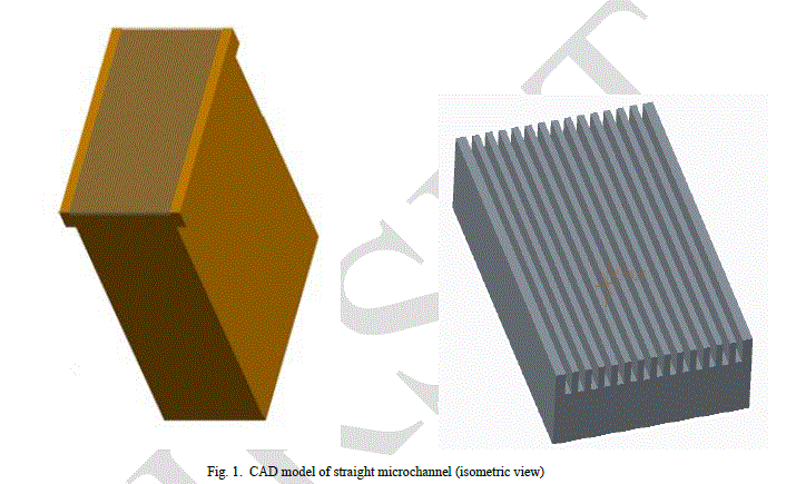
| According to Kandlikar and Grande [4], D is the diameter for circular channels. If the channel is not circular, it may be the ratio of four times cross section area to perimeter in case of rectangular, triangular and trapezoidal channels. As can be seen from Table 1.1, Therefore microchannel is defined as a channel with hydraulic diameters in the range of 10μm to 200μm. The main advantage of microchannel heat sink is large wetted area i.e., large surface area for heat transfer in small space which leads to a very high heat transfer rate. [6]. Most commonly used type of microchannel is of rectangular cross section because it is easy to manufacture & gives maximum wetted area. The schematic figure of straight microchannel shown in fig.1. |
 |
| Terminology, |
| Which are helpful during calculation of theoretical results. |
| a. Aspect ratio: |
| Aspect ratio defined as ratio of longer side of channel to the shorter side of channel [6]. |
 |
| For straight microchannels it has found out to be 507 μm for rectangular microchannel. |
| c. Nusselt number: |
| Nusselt is the measure of convective heat transfer. Higher the Nusselt number higher will be the value of convective heat transfer coefficient and hence higher will be the heat removal rate. According to the S.V.Garimella [3],the relation for average Nusselt number for constant heat flux at bottom and other three wall is adiabatic heating of microchannel is as follows, |
 |
| h. Pressure drop: |
| It occurs mainly due to the friction offered by the channel walls to the flow of water. Mathematical relationship can be given as [6], |
 (12) (12) |
IV. EXPERIMENTAL SET-UP AND EXPERIMENTS |
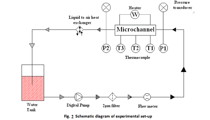
| The schematic diagram of experimental setup is as shown in figure 2. The important elements of the setup are microchannel test module, computerized peristaltic pump, thermocouples, heater, water tank, reservoir, submersible pump, digital temperature indicator, filter and pressure transducer [9-10]. |
 |
| Working: |
| Water from the tank is pumped to the reservoir with the help of submersible pump. Since, the flow rate provided by the submersible pump (8600 ml/min) is very high as compared to maximum flow rate provided by the peristaltic pump (BT600L) (0.006 - 2300ml/min) with speed precision is 0.1 rpm, accuracy 0.5%. Hence, Drain port is provided to the reservoir at the level just below the inlet port. The drain port also serves the purpose of maintaining constant head. Water from the upper reservoir is pumped by the peristaltic pump. Water is filtered by the filter mounted in between peristaltic pump and manifold. A manifold made from acrylic material for holding the heat sink securely in place and it’s have transparency for good aesthetic view . The cover plate on the heat sink top surface formed closed microchannels. A silicon sealant in the housing maintained a leak proof seal. The flow rate based on the tube diameter and pump RPM is used to get the desired flow rate. Water from the peristaltic pump flows to the manifold and then finally passes to the tank. Inlet plenum is manufactured in such a way that the air should be removed from the manifold during the flow. For getting the temperature readings at different location, thermocouples (K Type) are mounted at inlet plenum, outlet plenum, heater surface, and substrate. Thermocouple wires are connected to the digital temperature indicator of range 0 to +200°C with resolution of 0.01°C and accuracy ± 0.5% of range ± 1°C from 0 to +200°C to get the direct temperature reading. |
| For finding the pressure drop across the microchannel two pressure ports are provided. One port is in inlet plenum and other is at outlet plenum. Pressure drop across the microchannel is measured with the help of differential pressure meter is ideally suitable for pressure measurements in the range 0 to 100 hPa. Testo 735's differential pressure measurement is temperature-compensated for accurate readings. Readings can be displayed in Pascal over the whole measurement range. Magnets at the back of the instrument enable hands-free operation, which is connected in between these pressure ports. The test module consists of a microchannel heat sink, housing, cover plate, and 2 cartridge heaters for heating the substrate. 2 cartridge heaters each of 70 W is used, two 9 mm diameter holes were drilled into the lower portion of the heat sink to accommodate the cartridge heaters. They are inserted in the substrate from bottom side so that one end of the heater is very close to the base of channel. The perfect contact between heater and substrate is achieved by the thermal grease. |
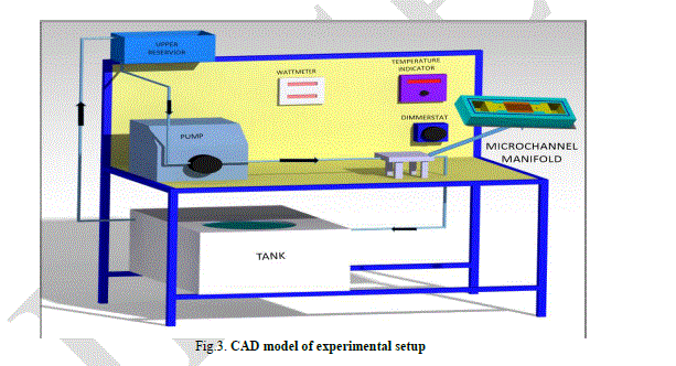
| For supplying the required power to the heater, these cartridge heaters were connected in parallel and powered by a DC power supply unit, Power dissipation by the cartridge heaters was measured by a wattmeter. With the help of digital voltmeter and ammeter power provided to the heater is calculated. The experiments were performed with constant heat fluxes applied at the bottom surfaces of heat sink and other three surfaces is assumed to be adiabatic. The experimental results have been compared both with theoretical predictions from the literature and the results obtained by numerical modelling under the same thermal boundary conditions at the inlet and outlet of the microchannel. The CAD model of experimental set up is as shown in figure 3. Whose working is same as described in above paragraphs. |
 |
V. DISCUSSION OF RESULTS |
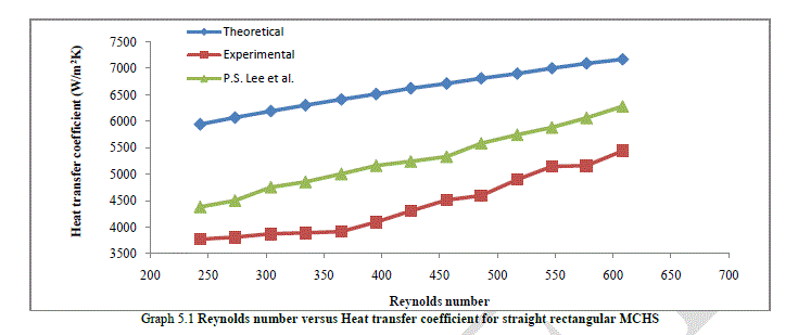
| From graph 5.1, it is observed that for higher flow rates experimental value is closer to the theoretical results and compared with the graph of P. S. Lee et al. [5] which is draw by using correlation given in journal paper. The heat transfer losses to the surrounding atmosphere due to radiation and conduction losses through acrylic are not taken into account for calculation of the theoretical heat transfer coefficient. Hence, there is deviation observed between theoretical and experimental value. |
 |
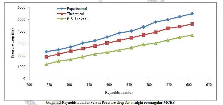
| From graph 5.2, it is observed that actual pressure drop is more than theoretically obtained value. There is difference in values since, pressure drop are measured across the manifold and theoretical values are calculated only for microchannel. The addition pressure drop is due to expansion and contraction experienced by water in manifold. Also it compares with a P. S. Lee et al. [5] journal paper. |
 |
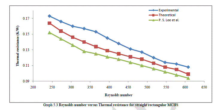
| From graph 5.3, it is observed that thermal resistance deceased with the increase in Reynolds number for experimental, theoretical and P. S. Lee et al. [5] graph which is drawn by correlation given in journal paper, also experimental value is more than that of theoretical. This is happen due to heat supplied to the microchannel increases and temperature difference of water between inlet and outlet of microchannel is decreased, hence according to Fourier law of conduction and Newton’s law of cooling the thermal resistance is decreased as Reynolds number increases. |
 |
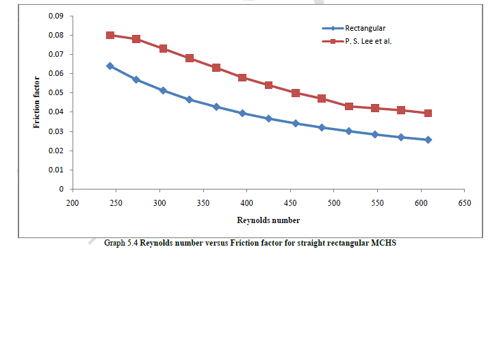
| From graph 5.4, it is observed that friction factor deceased with the increase in Reynolds number, this was compared with a P. S. Lee et al. [5] journal, It’s happened because of thin boundary layer developed at microchannel surface is increases and also time spend by water in microchannel is decreases as Reynolds number increases. Due to layer of water, the friction which is occurred at low Reynolds number is high as compared with high Reynolds number. |
 |
VI. CONCLUSION |
| 1. It is found that the experimentally determined Reynolds number in microchannels is lower than that predicted by the theoretical analysis. |
| 2. From experimentation and theoretical result, it can be concluded that straight microchannel heat sink gives better result at Reynolds number from 400 to 450 and flow rate is in between 320ml/min and 350ml/min. |
| 3. Microchannel heat sinks dissipate large amounts of heat with relatively little surface temperature rise. |
| 4. As Reynolds number increases; the heat transfer coefficient, pressure drop and pumping power increases while thermal resistance and friction factor decreases. |
| 5. To enhance the heat transfer in microchannel heat sink, it is necessary to study simultaneous effects of various parameters like size of channel, shape of channel, fluid properties, Reynolds number, friction factor, pressure drop, pumping power etc. |
| 6. In the microchannel, the local heat transfer coefficient h varies with the channel size, cross section of channel, shape of channel, fluid properties and the fluid flow arrangement. |
| 7. It is found that the experimentally determined Nusselt number in microchannels is lower than that predicted by the theoretical analysis. |
| NOMENCLATURE |
| h = Heat transfer coefficient |
| A = Heat transfer surface area |
| Dh = Hydraulic diameter |
| k = Thermal conductivity |
| Nu = Nusselt Number |
| Pr = Prandtl number |
| Re = Reynolds number |
| áùà= Mass flow rate |
| u/v/w/V = Velocity |
| T = Temperature |
| P = Perimeterρ = Density |
| Cp = Specific heat at constant pressure |
| μ = Dynamic viscosity |
| α = Aspect ratio |
| f = Friction factor |
| ΔP = Pressure drop |
| Wch = Channel width |
| Ww = Fin width |
| Hch = Channel height |
| N = Number of channel |
| Rth = Thermal resistance |
| Ppump = Pumping Power |
| Q = Discharge |
| Po = Poiseuille number |
| Hsub = Height of substrate |
| hyd = Hydrodynamic / hydrodynamically |
| th = Thermal/thermally |
| MCHS = Micro Channel Heat Sink |
| cs = Cross section |
| C1, C2, C3, C4 = Constant |
| avg. = Average |
References |
|