ISSN ONLINE(2319-8753)PRINT(2347-6710)
ISSN ONLINE(2319-8753)PRINT(2347-6710)
|
Mayurkumar kevadiya 1, Hemish A. Vaidya 2 Student, Department of Mechanical Engineering, Government College of Engineering, Valsad, Gujarat, India1 Assistant Professor, Department of Mechanical Engineering, Government College of Engineering, Valsad, Gujarat,India2 |
| Related article at Pubmed, Scholar Google |
Visit for more related articles at International Journal of Innovative Research in Science, Engineering and Technology
Our study focuses primarily on designing the blade for regions of low wind power density. The aerodynamic airfoils of wind turbine blades have crucial influence on aerodynamic efficiency of wind turbine. This involves the selection of a suitable airfoil section for the proposed wind turbine blade. In this paper NACA 4412 airfoil profile is considered for analysis of wind turbine blade. Geometry of the airfoil is created using GAMBIT 2.4.6. And CFD analysis is carried out using FLUENT 6.3.26 at various angles of attack from 0° to 12. The coefficient of lift and drag values are calculated for 1 ×10⁵ Reynolds number
Keywords |
| Airfoil; Angle of attack; coefficient of drag; coefficient of lift; computational fluid dynamics |
INTRODUCTION |
| An airfoil is defined as the cross section of a body that is placed in an airstream in order to produce a useful aerodynamic force in the most efficient manner possible. The cross sections of wings, propeller blades, windmill blades, compressor and turbine blades in a jet engine, and hydrofoils are example airfoils. The basic geometry of an airfoil is shown in Figure 1. [1] |
 |
II. LIFT AND DRAG |
| Lift on a body is defined as the force on the body in a direction normal to the flow direction. Lift will only be present if the fluid incorporates a circulatory flow about the body such as that which exists about a spinning cylinder. The velocity above the body is increased and so the static pressure is reduced. The velocity beneath is slowed down, giving an increase in static pressure. So, there is a normal force upwards called the lift force. The drag on a body in an oncoming flow is defined as the force on the body in a direction parallel flow direction. For a windmill to operate efficiently the lift force should be high and drag force should be low. For small angles of attack, lift force is high and drag force is low. If the angles of attack (α) increases beyond a certain value, the lift force decreases and the drag forces increases. So, the angle of attack plays a vital role. Lift and drag is presented in figure 2. |
 |
III. AIRFOIL DESCRIPTION |
| An airfoil means a two dimensional cross-section shape of a wing whose purpose is to either generate lift or minimize drag when exposed to a moving fluid. The word is an Americanization of the British term aerofoil which itself is derived from the two Greek words Aeros ("of the air") and Phyllon ("leaf"), or "air leaf". |
| The NACA four digit wing sections define the profile by: |
| 1. One digit describing the maximum camber as percentage of the chord |
| 2. One digit describing the distance of maximum camber from the airfoil leading edge in tens of percents of the chord |
| 3. Two digits describing maximum thickness of the airfoil as percent of the chord. [2] |
IV. MODELLING AND SIMULATION |
| Airfoil used in the study is shown in figure 3. For the flow analysis of the wind turbine blade mesh is created in the GAMBIT software. Figure 4 shows the meshing drawing of the airfoil below. [3] |
 |
 |
| FLUENT it set little parameters which are: |
 |
| V. LIFT AND DRAG |
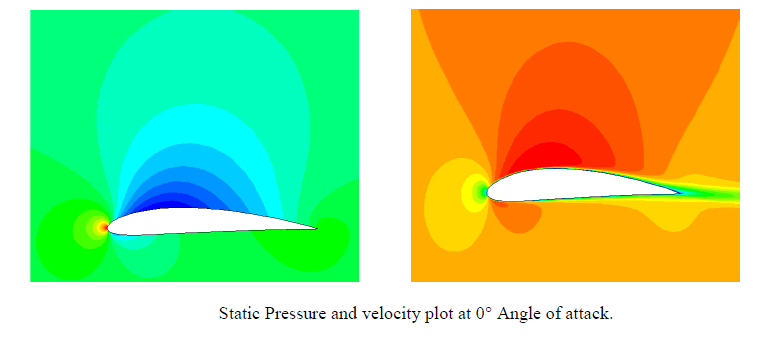
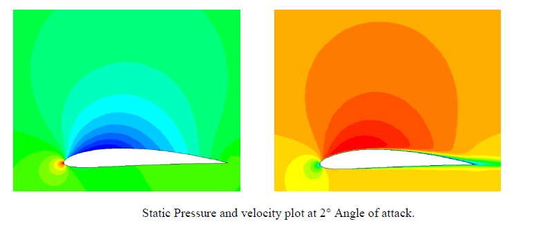
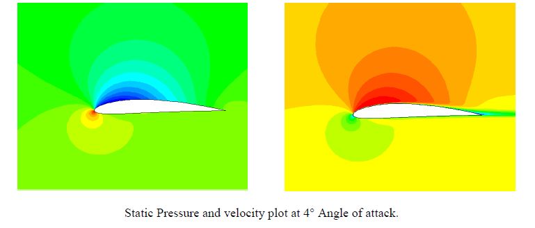
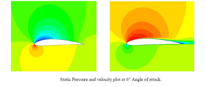
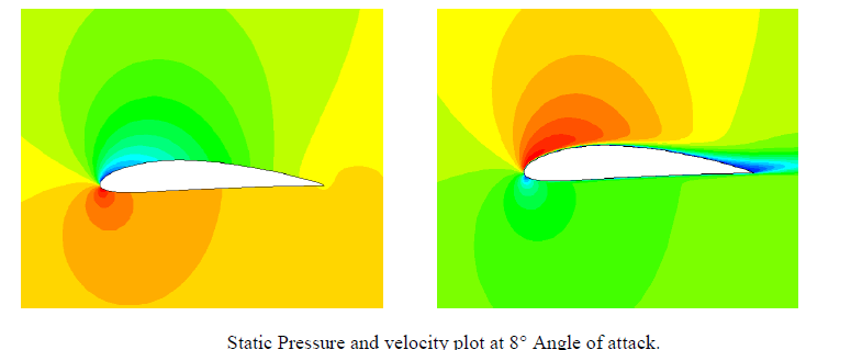
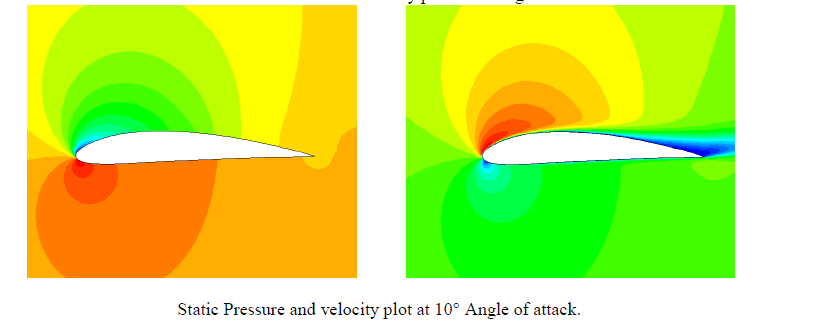
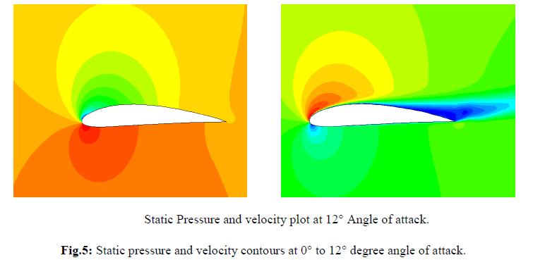
| From the contours, we see that there is a region of high pressure at the leading edge (stagnation point) and region of low pressure on the upper surface of airfoil. From Bernoulli equation, we know that whenever there is high velocity, we have low pressure and vice versa. Figure 1 to 6 shows the simulation outcomes of static pressure at angles of attack 0° to 12° with spalart allmaras model. The pressure on the lower surface of the airfoil was greater than that of the incoming flow stream and as a result it effectively “pushed” the airfoil upward, normal to the incoming flow stream. |
 |
 |
 |
 |
 |
 |
 |
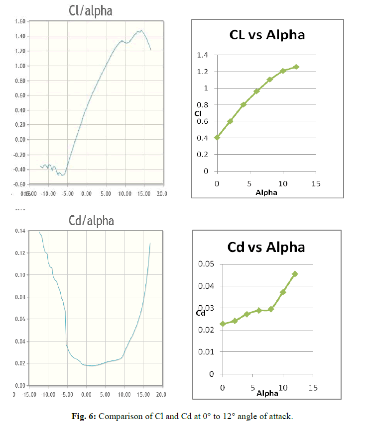
| The curves of the lift and the drag coefficient are shown for various angles of attack, computed with spalart-allmaras model and compared with data 0f NACA 4412 for Re = 1 × 10⁵.[4] |
 |
VI. CONCLUSION |
| The coefficient of Lift and drag is calculated for this NACA 4412 series for the angle of attack 0° to 12°. The coefficient of Lift/Drag ratio increases with increase in Angle of attack up to 8°. After 8°, Lift/Drag ratio decreases with increase in Angle of attack. |