ISSN ONLINE(2319-8753)PRINT(2347-6710)
ISSN ONLINE(2319-8753)PRINT(2347-6710)
| Masanam@Magesh. M1, Manimaran. S2, Murali. M3 Department of Mechanical Engineering, Magna College of Engineering, Magaral, Chennai, India |
| Related article at Pubmed, Scholar Google |
Visit for more related articles at International Journal of Innovative Research in Science, Engineering and Technology
Nowadays artificial implants have their major role in the Replacement Surgery of Human knee , Hip and other Bones of the human body.These implants will replace the defected knee or any other part of bones in the human body to do their functional role as same. Normally Human knee is the hinge joint consist of Femur and tibial bone connected together with the ligament structure. This consists of flexion and tibial rotation which is helps in the human body locomotion from one place to another. In this paper it is discussed about the brief of human gait cycle and along with artificial prosthesis development with the help of the jigs and fixtures also here it is shown about the manufacturing drawings , models , of the tibial and femoral jigs and Meshing of the Prosthesis parts done using CATIA V5 software package.
Keywords |
| Artificial knee, knee Prosthesis , Flexion ,Femoral jigs , Gait Cycle , Tibial Jigs. |
INTRODUCTION |
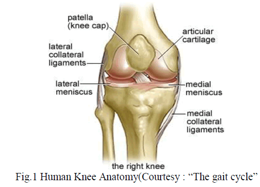
| The knee is one of the largest and most complex joints in the body. The knee joins the thigh bone (femur) to the shin bone (tibia) as shown in Fig.1. The smaller bone that runs alongside the tibia (fibula) and the kneecap (patella) are the other bones that make the knee joint.Tendons connect the knee bones to the leg muscles that move the knee joint.. Ligaments join the knee bones and provide stability to the knee. The anterior cruciate ligament prevents the femur from sliding backward on the tibia (or the tibia sliding forward on the femur).The posterior cruciate ligament prevents the femur from sliding forward on the tibia (or the tibia from sliding backward on the femur).The medial and lateral collateral ligaments prevent the femur from sliding side to side.Two C-shaped pieces of cartilage called the medial and lateral menisci act as shock absorbers between the femur and tibiaNumerous bur sae, or fluid-filled sacs, help the knee move smoothly. |
 |
Gait cycle: |
| The Term Gait cycle is Defined as the Series of rhythmic, alternative movements of lower limbs, upper limbs with the trunk leading to forward progression of the centre of gravity. The complete cycle start from the time of one foot touch the ground to the time the same foot touch the ground again. Usually gait cycle consist of two phases namely Stance Phase and Swing Phase. |
 |
| 1. Stance Phase: Usually stance phase deals with the initial contact of the Foot to the ground to toe off. It works nearly about 60% of the gait cycle.The period of time when the foot is in contact with the ground. |
| I. Initial Contact : Duraing at initial contact, the knee is extended and the ankle is neutral (or slightly plantar flexed) Normally, the heel contacts the ground first (in patients with pathological gait patterns, the entire foot or the toes contact the ground initially) |
| II. Loading Response :Loading response corresponds to the gait cycle's first period of double limb support & ends with contra lateral toe off , when the opposite extremity leaves the ground. during loading, knee flexes 15 deg while ankle plantar flexes 15 degrees, which is an energy-conserving mechanism throughout first phase of stance, hamstrings and ankle dorsiflexors remain active quadriceps and gluteal muscles act during loading and throughout early midstance to maintain hip and knee stability. |
| III. Mid-stance Phase : The next phase is the mid-stance phase. In this part of the gait cycle which represents 30 percent of the cycle, your body weight passes over your foot as the body comes forward. This is where your foot (in this case the right foot) supports your body weight. |
| IV. Terminal Stance : The second half of the single support from 30 to 50% of the gait cycle and is defined as the time from heel rise until the other limb makes contact with the floor. During this phase body weight moves ahead of the forefoot.The heel is raised as the body moves forward over the stance limb.The hip is in hyperextension, internal rotation, and adduction. |
| V. Pre-swing :The final double support stance period which is defined from the time of initial contact with the contra lateral limb to ipsilateral toe-off. |
2. Swing Phase : |
| Swing phase is called the “non-weight bearing” phase Begins as soon as the big toe of one limb leaves the ground (after toe off), and finishes just prior to heel strike or contact of the same limb. Swing phase consists of: Initial swing (acceleration) , Mid-swing , Terminal swing (deceleration). The period of time when the foot is not in contact with the ground. In those caseswhere the foot never leaves the ground (foot drag), it can be defined as the phase when all portions of the foot are in forward motion |
| I. Initial Swing :The initial third of the swing phase from 60 to 73% of the gait cycle as defined from toe-off to when the swing limb foot is opposite the stance limb.Forward momentum is provided by the ground reaction to the push-off action (when the heel is off the ground but the toes are in strong contact with the ground) |
| II. Mid swing :The middle third of the swing phase from 73 to 87% of the gait cycle as defined from the time the swing foot is opposite the stance limb to when the tibia is vertical. Begins from maximum knee flexion (when the swing limb is under the body) until the swing limb passes the stance limb and the tibia becomes in a vertical position. |
| III. Deceleration:The final third of the swing phase from 78 to 100% of the gait cycle as defined from the time when the tibia is vertical to initial contact. The momentum slows down as the limb moves into the stance phase again. |
Material for the jigs and Fixtures of Prosthesis : |
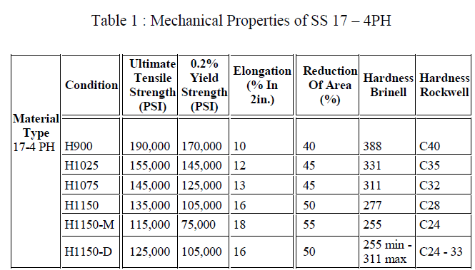
| The jigs and fixtures of both tibia and femoral are made up of Stainless Steel 17-4ph. This 17-4 ph Stainless Steel is a precipitation hardening martens tic stainless steel. Typical 17-4 ph usage is seen in applications requiring high strength and a modest level of corrosion resistance. Strength and toughness desired can be manipulated by temperate range in the heat treatment process. The Major applications of this materials includes Pump Shafts ,Oil Patch Mechanical Seal, Aerospace |
Tibial and Femoral jigs : |
| Jigs and fixtures are production work holding devices designed to hold, support, and locate a work piece. A jig guides the cutting tool with a drill bushing. A fixture references the cutting tool with a set block and feeler, or thickness gauges. Jigs are divided into two general classes: drill jigs and boring jigs. In this work we have modelled and manufactured the tibial and femoral jigs which are used for the manufacturing of the knee prosthesis. |
 |
| Both tibial and femoral jigs consist of numerous components such as cutting block , hammering dome, IM rod post , stylus scale and for femoral jig left side and right side holdermoving scale , etc. Initially all the models are done using modelling software after that it has been converted in to Manufacturing drawings and its converted in to machined components. |
| 1. Tibialjigs :Fig 3 and Fig 4 is showing about the Manufacturing drawings of the Tibial jigs obtained after 3D Modelling in the software by using the Drafting tool. With the help of this drawings the components are Machined using the CNC Machine. |
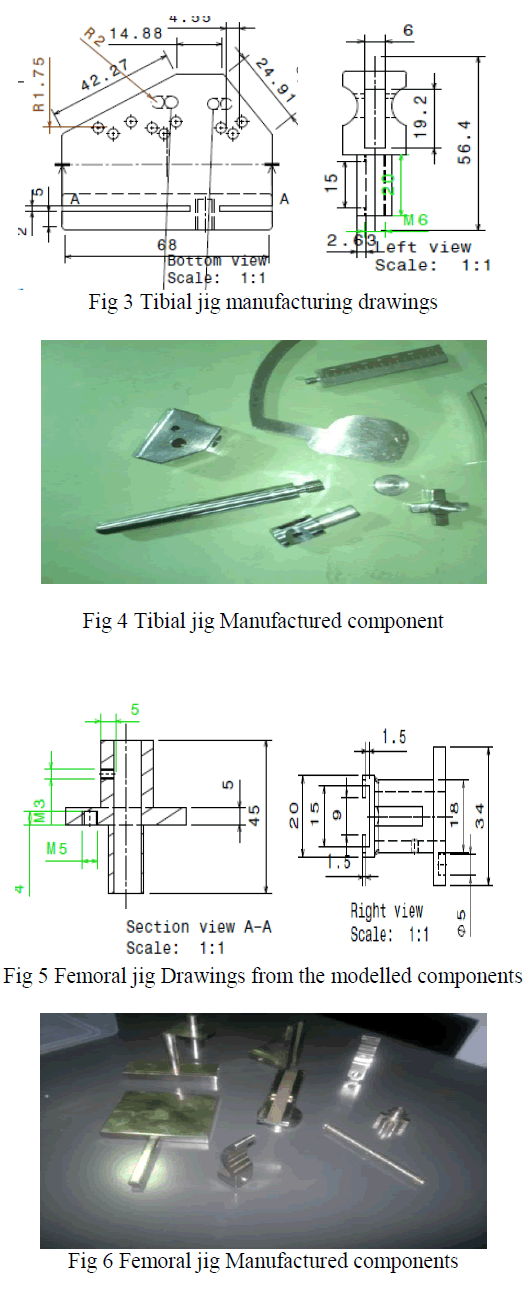 |
| Fig 5 and Fig 6 is showing about the Femoral jig Manufacturing Drawings and Machined Components using Stainless Steel 17-4PH. With the machined tibial and femoral jigs the Prosthesis is Developed as shown below. |
Prosthesis |
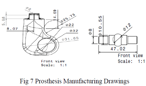
| After manufacturing of both the tibial and femoral jigs the prosthesis has to develop with the help of the jigs and fixtures. This prosthesis is made up of Bio materials such as Ti 64 and UHMWPE (ultra high molecular weight polyethylene) and SS 17 -4PH. The Mechanical properties of the SS17 – 4PH has been discussed already in the Table 1. Ultra-high-molecular-weight polyethylene (UHMWPE) is a subset of the thermoplasticpolyethylene. Also known as high-modulus polyethylene, (HMPE), or high-performance polyethylene (HPPE).it has extremely long chains, with a molecular weight usually between 2 and 6 million. The longer chain serves to transfer load more effectively to the polymer backbone by strengthening intermolecular interactions. This results in a very tough material, with the highest impact strength of any thermoplastic presently made. EOS Titanium Ti64 is a pre-alloyed Ti6AlV4 alloy in fine powder form. |
| This well-known light alloy is characterized by having excellent mechanical properties and corrosion resistance combined with low specific weight and biocompatibility. This material is ideal for many high-performance engineering applications, for example in aerospace and motor racing, and also for the production of biomedical implants. Parts built in EOS Titanium Ti64 fulfil the requirements of ASTM F1472 regarding maximum concentration of impurities.the major applications of this Ti 64 are direct manufacture of functional prototypes small series products, individualised products or spare parts parts requiring a combination of high mechanical properties and low specific weight, e.g. structural and engine components for aerospace and motor racing applications, etc. biomedical implants. |
 |
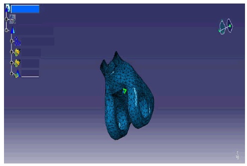
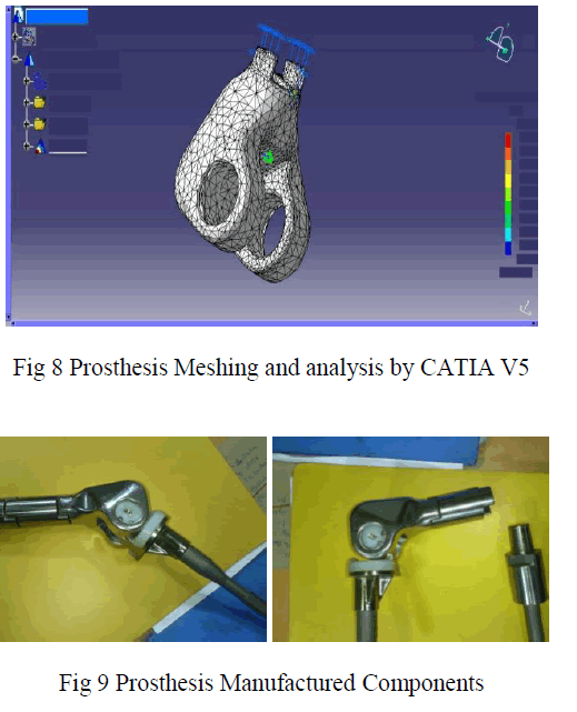
| The analysis of the Femoral condyle is done with the CATIA V5 Analysis by using the analysis tool in the software. After applying the material in this it is meshed fully to the nodes. And one end is fixed and in another end the distributed force of -2000N is applied and the results has been shown here. |
 |
 |
II. CONCLUSION |
| This research on Bio medical implants have to get more concentrated by the upcoming researchers to meet the future issues on the Bone replacement surgery. Also this development of the prosthesis will not meet the requirement of every person. It may vary from person to person depend upon the loading conditions and the human Gait cycle of the individual. Also the usage materials such as TI 64, SS 17-4PH has to improve in the stage of Nano technological adaptation to reduce the prosthesis weight and with improved life time by high wear and fatigue resistance in working conditions. |
III. ACKNOWLEDGEMENT |
| We like to Express our warm thanks to Non-Ferrous Materials technology Development Centre , An Autonomous R&D Centre , under ministry of Mines , Kanchanbag Hyderabad for giving continuous support for this Research. |
| Masanam@Magesh. M1, Manimaran. S2, Murali. M3 Department of Mechanical Engineering, Magna College of Engineering, Magaral, Chennai, India |
| Related article at Pubmed, Scholar Google |