International Journal of Innovative Research in Science, Engineering and Technology
ISSN ONLINE(2319-8753)PRINT(2347-6710)
ISSN ONLINE(2319-8753)PRINT(2347-6710)
Ruba.C1, Balaji.T2
|
| Related article at Pubmed, Scholar Google |
Visit for more related articles at International Journal of Innovative Research in Science, Engineering and Technology
This letter presents for the first time the application of multilevel dc-link inverter to overcome the problem of partial shading of individual photovoltaic (PV) sources which are connected in series. The “PV permutation algorithm,” as a new method, is developed for the control of the inverter so as to extract the maximum power form each PV source under partial shading and to deliver all that power to the load. The algorithm is based on combination of the direct pulsewidth modulation, the sequential permutation PV sources, and the output generation to control the multilevel dc-link inverter. The algorithm is applied successfully to a seven-level inverter with separate maximum power point tracking algorithm for each PV source and under nonuniform irradiance (partial shading). Digital processing unit F28335 eZdsp is used to control the PV system in the real-time mode, and MATLAB–Simulink real-time data exchange is employed to display the extracted power and to control the system parameters via a designed graphical user interface window. The implementation results are presented.
INTRODUCTION |
| PARTIAL shading of individual photovoltaic PV) sources, which are connected in series, reduces the current and requires incorporation of bypass diodes in order to avoid damage of individual PV sources. Consequently, the power delivered to the load is reduced significantly. When the power sources are connected in series via dc/dc converters, as suggested in [1], the control of duty cycle compensates for reduction of the irradiation of the shaded source which does not then operate at the MPP. Such a control is functional up to the minimum level of irradiation below which the current of the shaded source cannot be kept at the same level as that generated by other nonshaded sources. If the irradiation is reduced below the minimum level, then the shaded source has to be bypassed to allow nonshaded sources to operate at maximum power point (MPP). Such a topology cannot maintain all seriesconnected PV sources operating at their MPP under partial shading. Alternative approach, so-called generation control circuit (GCC) structure [2], is based on the multistage buck–boost converter circuit. In this scheme, only one switch is in off-state at any instant, while other switches are bypassed by free-wheeling diodes, and therefore, there is a restriction on nonconduction intervals of other switches. In other words, the switches cannot be independently controlled. Consequently, finding the MPP of one PV source does not mean that other seriesconnected PV sources operate at their MPP. For this reason, an optimal duty ratio has to be found by “tracking algorithm” in order to deliver the largest power to the load. Introduction of a multilevel inverter in PV power system enables each PV source to be controlled separately. Among all variants of multilevel inverters, the “cascaded H-bridge inverter” is most commonly used due to its modular circuit structure. The power of each PV source can be maximized by allocating a maximum power point tracking (MPPT) algorithm for each PV source. This approach has been applied in [3] only in an experimental model where each PV source was emulated by a series connection of dc source and resistance. Such a representation, however, does not reflect the proper behavior of the PV source, especially under partial shading. |
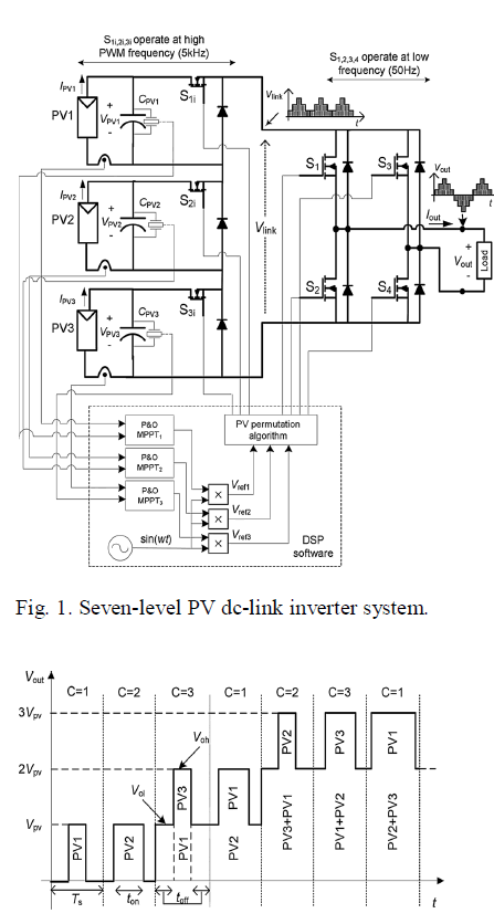
| In [4], the PV dc-link inverter is operated successfully via pulse width modulation (PWM), but the results obtained under different partial shading levels have shown that the employed PV sources were not at their MPPs. In this letter, the PV multilevel dc-link inverter with the PV permutation algorithm is used to overcome the problem of uneven irradiance. A PV system with seven-level dc-link inverter is shown in Fig. 1. Each PV unit consists of a PV source, terminal dc-link waveform Vlink. The switches S1–S4 in the H-bridge operate at low frequency to form the desired ac output. |
II. NOVEL CONTROL ALGORITHM |
| The proposed algorithm involves three stages: direct PWM, sequential permutation of PV sources, and the output generation. The details of the first stage are described in [5]. It reduces the computational time compared with space-vector PWM methods and is used here for determining the required low and high output voltage levels (Vol and Voh) and their time intervals (toff and ton) within each PWM switching cycle of period Ts . The second stage is based on the work described in [6] for the system formed of two PV sources. However, the application of sequential permutation in systems containing more than two PV sources is more complex and a generalized approach to sequential permutation is outlined in Section II-A. The third stage “the output generation” provides a novel solution to the partial shading and is described in Section II-B. A. Sequential Permutation of PV Sources All PV sources which form the output PWM voltage are sequentially permutated per each consecutive PWM switching cycle according to the numerical count C = 1, 2, . . ., n (where n denotes the total number of PV sources), as illustrated in Fig. 2.The PV source which sequentially comes in turn at the highest voltage level is the only one which is controlled at a particular switching cycle, while other sources are used to build the appropriate voltage level determined in the first stage (the direct PWM). The benefits of such a procedure are the following: 1) all PV sources of the system are used equally, so under symmetrical irradiance of PV sources, they produce equal amount of power,and the switching losses of transistors associated with each PV TABLE I OUTPUT GENERATION FROM TWO PV SOURCES sources are equal; 2) it allows to achieve symmetrical positive and negative half-cycles of the output voltage waveform under partial shading, i.e., when PV voltages are different; and 3) it enables a reduction of the voltage ripple on PV capacitors. |
 |
| Fig. 2. Numerical PV source permutation mechanism. |
B. PV Output Generation |
| As shown in Fig. 1, the control unit of the PV system includes a perturbation and observation (P&O) MPPT block for each PV source. These provide a separate P&O tracking algorithm and the PI control for each PV source. The output signals of these blocks are multiplied by unity sinusoidal signal to form ac reference signals vref1 , vref2 , . . ., vref (n) . These reference signals are used to control the inverter switches by applying the direct PWM (the first stage in the algorithm) and the output generation. The direct PWM normalized reference voltage (p.u. value) is given as where VMPP is the value of MPP voltage at irradiance of 1000 W/m2 , and n denotes the total number of PV sources. |
| The integer part of the normalized reference voltage is defined as the normalized offset voltage and it is given as |
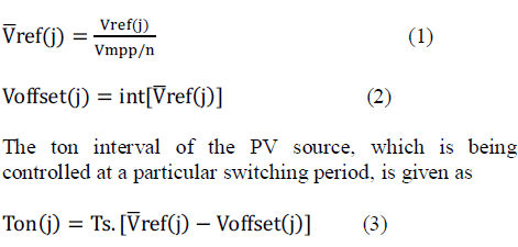 |
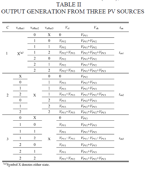
| Equation (3) can be derived by equating the approximate area of the graph “vref versus Time” with the corresponding area under the generated pulse within a cycle Ts [5]. Table I describes the principles of generating the output voltage in a system consisting of two PV sources. If C = 1, the source PV1 is controlled by applying direct PWM to vref1 in order to determine the required ton time. The role of vref2 is to determine Vol by checking voffset2. Similarly, when C = 2,then the PV2 is controlled through vref2 , and vref1 is used to determine the Vol . In the case of three PV sources (n = 3), the algorithm is accomplished in a similar fashion by applying permutation of the source indices C=1, 2, and 3. Table II describes the output generation in case of n = 3.Fig. 3 shows the flowchart of the PV permutation algorithm which is applied to the seven-level inverter operating with three PV sources. The flowchart indicates the main stages in the algorithm including the PV output generation which is described by Table II. In order to ensure a continual sequential permutation, the index C + k (where k = 1, 2) of offset voltage or source voltage is reset to C + k − 3 if the index value is greater than 3.The algorithm enables each shaded PV source to be recovered to its MPP without affecting other PV sources.At a given number of PV sources, the flexibility of control is improved by increasing the frequency modulation index Mf (= fs /f, where fs denotes the switching frequency and f is the required output frequency) as it enables each source to be controlled more frequently within a full ac cycle. |
 |
III. SIMULATION RESULTS |
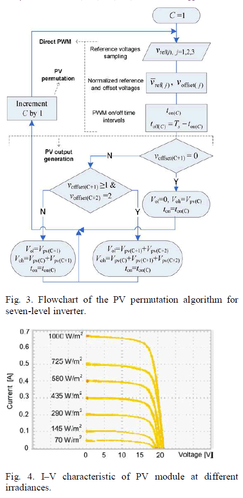
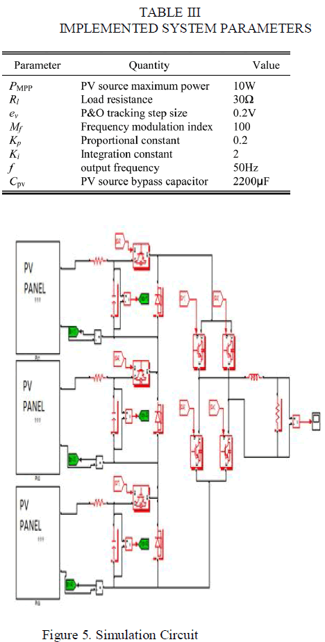
| The algorithm has been applied to a small-scale PV system formed of three PV sources, each rated at 10W, connected to a dc-link MOSFET-based inverter, as shown in Fig. 1. The measured I–V characteristics of the PV source are shown in Fig. 4 for different irradiance levels at room and surface temperatures of 21 âÃâæC and 38 âÃâæC, respectively [4].The dc-link inverter [7], [8] involves switches associated with PV sources, which operate at 5- kHz PWM frequency, and the H-bridge switches which operate at 50-Hz frequency. |
 |
 |
 |
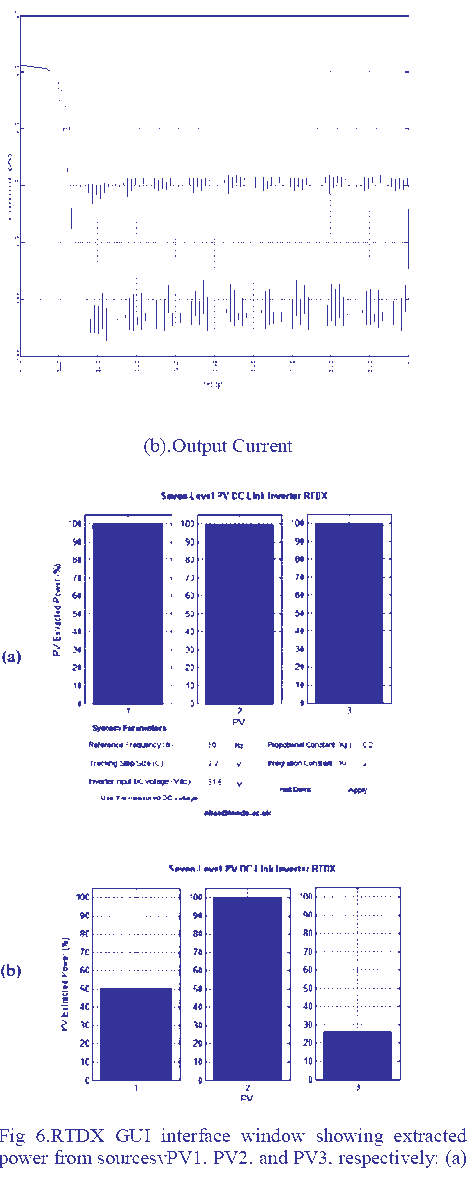 |
| 100% for all, (b) 50%, 100%, and 25% of the MPP at 1000W/m2 . |
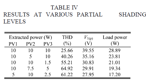 |
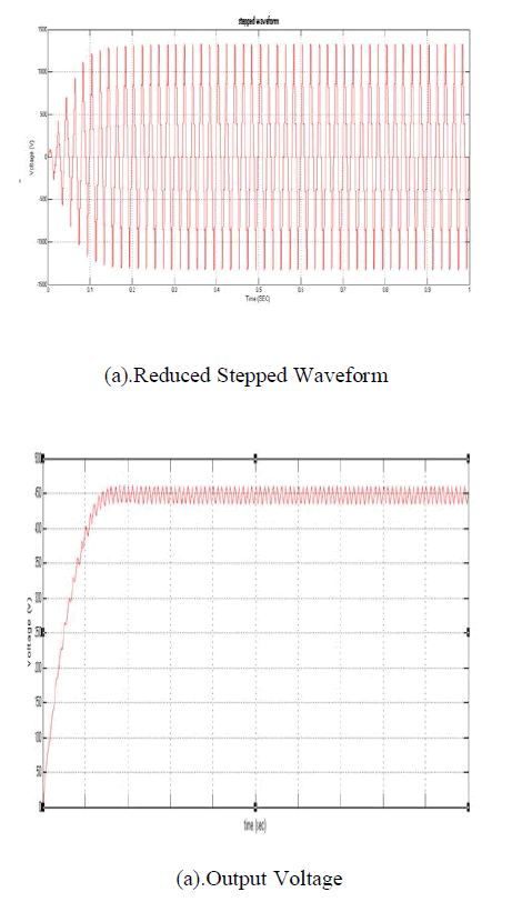
| The control algorithm is implemented using digital processing unit F28335 eZdsp in the real-time data exchange (RTDX) by MATLAB–Simulink. A graphical user interface (GUI) window is designed to display the extracted power from each source as a percentage of its rated power and to control the system parameters.Table III shows the system parameters applied in the experiment. The resulting voltage and current waveforms are shown in Fig. a,b and c respectively. The shaded PV sources do not affect the operation of nonshaded sources of the system, so they continue to deliver their maximum power to the load as illustrated in Fig. 6.Table IV describes the output in terms of the total harmonic distortion (THD), the amplitude of the fundamental harmonic V1(p) , and the load power as a function of extracted power. |
IV. CONCLUSION |
| The presented system incorporates a novel method of extracting the maximum power from each PV source to the load while maintaining the operation of all PV sources at their MPPs under partial shading. This is in contrast to the systems based on series-connected dc/dc converters or a multistage buck–boost system (GCC), where the operation of all PV sources cannot be maintained at their MPPs under partial shading. The presented system has been implemented with the seven-level inverter using processing unit F28335 eZdsp in the RTDX by MATLAB–Simulink. The output voltage waveforms under various partial shading levels were analyzed by fast Fourier transform and the results show low THD. |