ISSN ONLINE(2319-8753)PRINT(2347-6710)
ISSN ONLINE(2319-8753)PRINT(2347-6710)
Mrs. Sunita Ravi Kadali1, Prof Mrs. V.S. Jape*2
|
| Corresponding Author: Prof Mrs. V.S. Jape, |
| Related article at Pubmed, Scholar Google |
Visit for more related articles at International Journal of Innovative Research in Science, Engineering and Technology
Minimum element in the manufacturing of photovoltaic (PV) systems is the PV module. For most applications, it becomes necessary to group PV modules until the desired current and voltage levels are achieved.There may be variations in electric characteristics of PV modules due to manufacturing processes, differences in the orientations and inclinations of solar surfaces, temperature-effects, aging-related parametric drift and so forth. Because of mismatching, PV systems show additional losses.These additional losses are caused mainly due to the fault of Maximum Power Point Tracking (MPPT) of individual modules in presence of mismatching operating conditions. If a module becomes partially shaded by buildings or trees then module’s output is limited by the cell with the lowest output. The resulting loss of power is referred to as mismatch loss. They can be decreased by a DC-DC converter dedicated to each module is inserted, and each converter performs its own MPPT operation. This process is called Distributed MPPT (DMPPT).To proposed distributed MPPT control Mat-lab Simulink model of CMPPT and DMPPT run for various irradiance condition along with various value of resistances.This paper presents advantages of DMMPT in Mat-lab simulation over centralized MPPT. It is a low-cost high-efficiency dc–dc converter with maximum power point tracking (MPPT) functions & control.
Keywords |
| Bypass-Diode, blocking-Diode, Centralized & Distributed MPPT, DC-DC Converter, hotspot formation, Mismatch loss, |
INTRODUCTION |
| Renewable energy sources, which is significantly contributing to the sustainable energy supply. It becomes an emerging technology due to the continuous cost reduction and technological progress. The minimum element in the manufacturing of photovoltaic (PV)systems is the PV module; the power of one PV module is not enough. So PV modules are grouped until the desired current and voltage levels are achieved. The group of these PV modules is often composed of a number of series-connected modules (strings) arranged in parallel. Usually, it is assumed that cells in a PV field are of the same type, or even equal, then the PV field works in matching conditions. The cases include partial shadows, variations in electric characteristics of PV modules due to manufacturing processes, differences in the orientations and inclinations of solar surfaces, temperature effects, aging-related parametric drift and so forth. Because of mismatching, PV systems show additional losses. Most issues carried out about building integrated photovoltaic system performance show average losses of up to 25% in electricity production [1] These additional losses are caused mainly due to the fault of Maximum Power Point Tracking (MPPT) of individual modules in presence of mismatching operating conditions. They can be decreased by means of suitable electronics i.e. a DC-DC converter dedicated to each module is inserted, and each converter performs its own MPPT operation. This process is called Distributed MPPT (DMPPT).A formal DMPPT concept for PV arrays will be use. |
INFLUENCE OF PARTIAL SHADOWS ON PV SYSTEMS |
| There are small manufacturing tolerances, occasional minor damage due to cracking, and small temperature differences, depending on where cells are located in the module. If a module becomes partially shaded by buildings or trees, some cells receive more sunlight than others. In all cases the module’s output is limited by the cell with the lowest output. The resulting loss of power is referred to as mismatch loss. Small expected mismatch losses are covered by manufacturing tolerances. But additional losses can easily be caused by shading; the situation can worsen dramatically if one cell in a string fails to generate current. It then acts as a load for the other cells and starts to dissipate substantial power, which can lead to breakdown in localized areas of its p – n junction. Severe local overheating occurs, possibly causing cracking, melting of solder, or damage to the encapsulating material. This is known as hot-spot formation. Hot - spot failure is avoided by incorporating additional diodes known as bypass diodes. Blocking diodes(one in series with each string), to ensure that current only flows out of the modules and to prevent the batteries from discharging back through the modules at night [7].Some manufacturers include blocking diodes within their modules. An array is consisting of number of module, so it is major decision about how they should be interconnected .Modules can be connected in two MPPT topologies. |
| A. Centralized MPPT: - The centralized topology, in which all PV modules are connected in series to a single inverter with a centralize MPPT; all PV modules connected in series are forced to drive the same current as shown in fig.1. If they cannot drive this current, then their associated bypass diodes conduct. Although diodes protect PV modules from “hot-spot” effects, they introduce multiple maxima on the array power– current P–I curve, as shown in Fig. resulting in problems with MPPT. Even if the MPPT reaches the greatest power maxima the shaded PV modules would be acting as passive loads, significantly reducing the efficiency of the whole PV system. |
 |
| B. Distributed MPPT: - A DC-DC converter dedicated to each module is inserted, and each converter performs its own MPPT operation as shown in fig.2 .This process is called Distributed MPPT (DMPPT).There is interconnection between the associated dc–dc converters instead of PV modules. Therefore, each PV module can operate at its own optimal power and current, and all the available energy in the PV array can be delivered. Losses from shading of a single PV module are limited to that module; any unshaded modules nearby are unaffected. |
 |
| The advantages of DMPPT are better utilization, Mixing of Different sources becomes possible, Better protection of Power Sources, Better Data gathering, Greater safety during Installation and Maintenance are advantage of Converter-per-Panel (DMPPT). The factor comes first of all by DMPPT is cost. |
Cost Justification |
| ïÃÆÃË The hardware functionality of the modules could be standardised. They could be made in significant Volumes by a number of manufacturers. |
| ïÃÆÃË The advantages of greater efficiency and reliability would increase the return on the installation investment.[3] |
SIMULATION & RESULTS |
| The objective of work carried is to prove DMPPT is better than Centralized MPPT. For this we made many simulation model are as follows. |
| A. Photovoltaic module modelling: It is derived from a one-diode model with some parameters in the mathematical equation of solar cell. From data provided by all commercial datasheets, the method finds the nonlinear I–V and P-V characteristics for the single-diode photovoltaic (PV) model including the effect of shading. Taking the effect of irradiance and temperature into consideration, the output current and power characteristic of PV model are simulated using the proposed model. |
 |
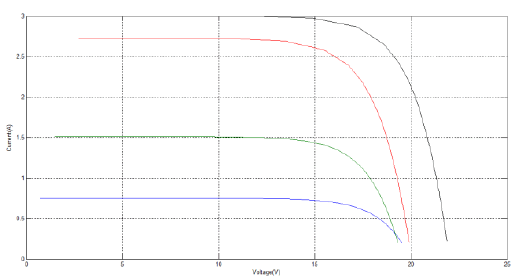
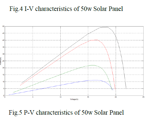
| The subsystem block in Fig.3 will be a basic PV module model of MATLAB-Simulink in this paper. In the subsystem block, port of out + is the positive terminal of the PV module, port of out− is the negative terminal of the PV module, port of S is the irradiance, and T is the temperature of the PV module. For various values of irradiance and temperature we can obtain various V-I and P-V characteristics. A PV module, 50W PV with 36 series-connected mono crystalline cells, is chosen to evaluate the proposed model in this paper. The electrical characteristics specifications under STC from manufacturer are shown in Table 1. |
 |
| To evaluate the availability of the proposed model, four measurement I–V curves and P–V curves of single 50W PV module are selected which gives the results of simulation using the proposed model. Testing conditions are irradiance at 250 W/m2 with module temperature at 25°C, irradiance at 500 W/m2 with module temperature at 45°C, irradiance at 900 W/m2 with module temperature at 50°C and, irradiance at 1000 W/m2 with module temperature at 25°C. Fig.4 and fig.5 shows V-I and P-V characteristics of panel from Mat-lab-Simulink respectively. |
 |
 |
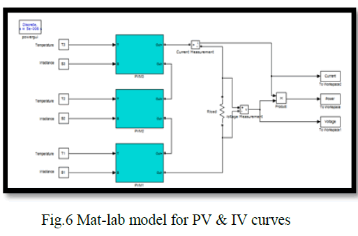
| B. Effect of non-uniform irradiance on Photovoltaic module of Photovoltaic array: To evaluate the performance of the proposed model under non-uniform irradiance conditions, three PV modules are connected in series to obtain the I–V and P–V characteristics. The corresponding diagram is shown in Fig.6. Three PV module models are employed are named PVM1, PVM2, and PVM3 respectively, and they have their individual inputs of temperature and irradiance. An adjustable resistance Rload is tied with the output of this series as load. The PV array simulation model allows us to investigate the characteristics of a PV array under various conditions of different irradiance and temperature. |
 |
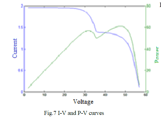 |
| Fig.7 is simulation results of PV array output power under the condition of non-uniform irradiance shows multi-peaks. No. of peaks depends on irradiance levels. |
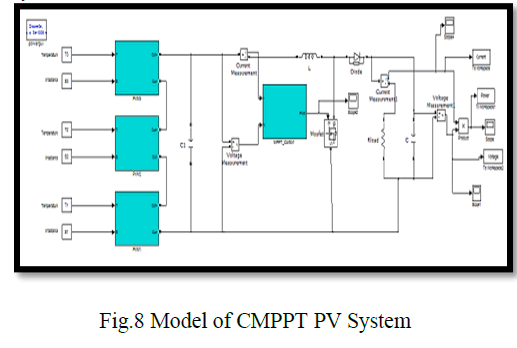
| C. Mat-lab Simulink model of centralized MPPT System |
 |
| D. Mat-lab Simulink model of Distributed MPPT System |
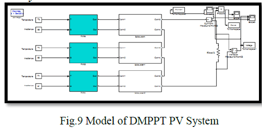 |
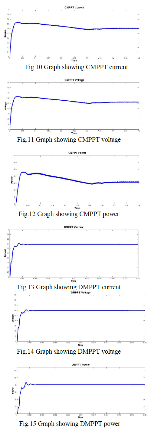
| Comparison Results: The fig.8 and fig.9 is mat-lab Simulink model of CMPPT and DMPPT respectively. To evaluate proposed distributed control MPPT Matlab Simulink model of CMPPT and DMPPT run for various irradiance condition along with various value of resistances. The simulation running conditions are S1 = 1000 W/m2, S2 = 800 W/m2, and S3 =524 W/m2. T1=T2=T3=32°C along with 90 Ohm resistance. The graph of current, voltage and power for CMPPT and DMPPT are shown respectively in fig10, 11,12,13,14 and 15. |
 |
CONCLUSIONS |
| It is an innovative concept of distributed control of the smart photovoltaic system. In the cases of the undesired performance problem (partial shadows, mismatching) of the photovoltaic system, electrical energy losses will be reduced and the system efficiency would be enhanced, as the DC-DC converter allows each photovoltaic module to work at its MPP independently from the rest of the photovoltaic modules. The DMPPT settles very early as compared with centralized MPPT .Centralized MPPT take 0.3 second to reach in stable state while DMPPT system reaches in stable state in 3 micro second. The output power has not pulsation as in centralized system. |
ACKNOW LEDGMENT |
| It gives me great pleasure to present this paper towards step up for fulfillment of project work in M.E. Electrical Engineering (Control System) course of University of Pune. I take this opportunity to convey my deepest thanks to my college to allow me to publish this paper. My special thanks to Prof. Dr. (Mrs.) N. R. Kulkarni Head of Electrical Engineering Department for her cooperation and support. I also express my gratitude towards all the faculties of the department of electrical engineering for their help. |