ISSN ONLINE(2319-8753)PRINT(2347-6710)
ISSN ONLINE(2319-8753)PRINT(2347-6710)
Nagamanikandan G, Rajadurai A
|
| Related article at Pubmed, Scholar Google |
Visit for more related articles at International Journal of Innovative Research in Science, Engineering and Technology
In this paper we present a design and development of a mobile robot with 5 axes manipulator and it is manipulated by visual servoing scheme which provides closed loop position control of end effector. Robots have made only less impact in application such as assembling, missile tracking, object grasping, part mating etc. This limitation is largely due to lack of sensor capabilities in a commercial robot system. It could be overcome by using vision sensor as a feedback unit to control the robot. The main disadvantage of conventional manipulator is, either it has a programmed spatial coordinates or time-consuming manual teaching of robot positions. Here, the motion of a 5 axes manipulator is not pre-programmed in the controller but the kinematics are generated by the fusion of information from vision sensor and distance measuring sensor. The navigation of this robot is accomplished by tracking the known patterns using vision sensor. In a conventional Industrial serial robot, due to moment of inertia at tip of the arm, inherent nature of sensor capabilities, wear and tear along the transmission system in joint space leads to inaccurate positioning of end-effector. These above flaws in positioning of end-effector could be completely eliminated by visual feedback control unit which increases overall accuracy of the system.
Keywords |
| Robotics, visual servoing. |
INTRODUCTION |
| The main task of a robot is to precisely positioning and orienting a tool in a given manner. Depending upon the application the configuration of a robotic manipulator is selected and designed based on the requirements. The most common manipulator design is a serial structure were the actuated joints path exist between the tool and ground. To position and orient tool task in space, requires a six DOF manipulator to manipulate the tool. Many tasks require less than six DOF. For example, tasks which employ an axis-symmetric tool do not require roll orientation. Some tasks require simple pointing orientation, a two DOF task e.g., planar robot or spatial point positioning, a three DOF task e.g., SCARA. In some cases, a two or three DOF manipulator will be used as modular sub-components in a larger manipulator system. For example, many six DOF serial manipulators consist of two sub-structures; a three DOF arm used to position the tool, and a three DOF wrist used to orient the tool. In this paper, a three DOF arm used to position and two DOF used to orient the end effector. The 5 Axes manipulators are mainly used in various industrial applications such as mechanical parts assembling, printed circuit board component assembly, grasping objects, part mating and also to assist the human via serving, cooking etc. |
| When programming the robot position control, the accuracy as well as the repeatability of the robots positioning must be extremely high, so that parts are to be assembled can be placed at positions and orientations within thousands of an inch of their desired position and orientation. For this reason, it is critical that the entire robotic assembly work cell be precisely calibrated for most assemblies to be successfully accomplished, but precisely calibrating the entire work cell is tedious and expensive. An alternative to precise calibration is to use vision sensor feedback during the assembly process as stated in [11]. |
| The commercial Industrial robots suffer from a fundamental disadvantage: lack of mobility. A fixed manipulator has a limited range of motion that depends on where it is bolted down. In contrast, a mobile robot would be able to travel throughout the manufacturing plant, flexibly applying its talents wherever it is most effective. A mobile robot is an automatic machine that is capable of movement in any given environment as described in [12]. Mobile robots have the capability to move around in their environment and are not fixed to one physical location. Because of this reason, the work volume of a mobile manipulator was infinite. |
BACKGROUND AND DEFINITION |
| A. Conventio nal Robots |
| Conventional robots can perform assembly and material handling jobs with high speed and precision but they cannot see what they are doing. Therefore the task work piece, and the work space of the robot is completely constrained or limited. And care should be taken for placing the work piece. These robots need structured work environment where all relevant points must be preprogrammed. |
| The problems of conventional robot manipulators may be summarized as: |
| 1. It is necessary to provide, highly structured work environments for robots. |
| 2. The limited accuracy of a robot frequently necessitates time-consuming manual teaching of robot positions. |
| 3. Mechanical dynamics in the robotâÃâ¬ÃŸs structure and drive train fundamentally constrain the minimum cycle time as stated in [4]. |
| B. Visual Servoing |
| Visual servoing is a modern approach to the control of robot manipulators that is based on visual perception of robot and work piece location. Visual servoing involves the use of one or more cameras and a computer vision system to control the position of the robotâÃâ¬ÃŸs end-effector relative to the work piece as required by the task. Visual servoing is to use visual information to control the pose of the robotâÃâ¬ÃŸs end-effector relative to a target object or a set of target features. Reference [4] [5] provides tutorial introduction to this topic. |
| C.Advantages of Visual Servoing |
| It doesnâÃâ¬ÃŸt need Prior information of the spatial coordinates of the work pieces. It doesnâÃâ¬ÃŸt require structured environment. It eliminates the manual teaching of the robot. The deficiencies of the mechanism would be compensated by the vision feedback which increases the desired accuracy and repeatability. |
| In Conventional robots, we acquire the image from the vision sensor and process it to get the information such as area, centroid, circularity and etc. about the feature of interest. In such systems visual sensing and manipulation are combined in open loop fashion, „lookingâÃâ¬ÃŸ then „movingâÃâ¬ÃŸ. These systems are static and the processing time is in the order of 0.05 to 1 second as stated in [4]. The accuracy of the „look- then-moveâÃâ¬ÃŸ approach directly depends on the accuracy of the vision sensor and the accuracy of the robot manipulator. An alternative to increasing the accuracy of these sub-systems is to use a visual-feedback control loop which will increase the overall accuracy of the system. Taken to the extreme, machine vision can provide closed-loop position control for a robot end-effector; this is referred to as visual servoing as described in [4]. |
METHODOLOGY |
| In this paper an attempt is made to design and development of a 5 axes manipulator were the angular position of the joint axes are controlled by vision sensor as a feedback device. The angular position of joint actuator of the manipulator is obtained from Cartesian coordinates of an end-effector. This manipulator consists of 5 DOF and 1 DOF for end-effector. Each joint is actuated by a separate actuator. Here, the actuator is servomotor which is actuated by applying proper PWM signal. To avoid the processing time as well as programming complexity all the joint actuators are actuated by USB servo controller. |
| After acquiring the image by using vision sensor it is fed to the computer through USB cable and the acquired image is processed by using suitable image processing software to determine the X, Y location of feature of interest [6] i.e., peg. Simultaneously, the distance measuring sensor measures the distance between the feature of interest and the peg. Since, the measured value is in analog form it has to convert into digital form by using ADC.it is a inbuilt peripheral of a controller were the incoming analog signal is converted into digital form and this digital signal „ZâÃâ¬ÃŸ is fed to the computer by using serial communication. Electronic and control system of this robot was shown in Fig. 1 |
 |
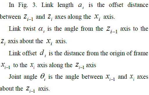
| If the range of Z is not within the reach of robot, then by using vision sensor depending upon the value X, Y of peg location processed from Image processing software the vehicle has to move towards left or right with respect to the location of peg at the same time the vehicle has to move forward depending upon the Z value, until Z equals or less than the reach of a manipulator. If the range of Z is within the reach of robot, then by using X,Y from vision sensor and Z from distance measuring sensor are fused together to generate joint angles by solving DH parameters[8] [9] [10]. Similarly, find the location of the hole and place the peg into the hole. |
| A. Robot Task |
| The task of a robot can be accomplished with respect to the various reference cartesian coordinate frames as shown in Fig. 2. The fusion of information from vision sensor and distance measuring sensor is used to locate the object coordinate frame Xo, Yo and Zo, with respect to object frame the vehicle will move towards the object until it reaches the reach of a robot. The base reference frame is formulated with respect to the camera reference frame. The joint actuators are controllably actuated continuously with respect to the visual information until the tool reference frame XT, YT and ZT reaches the object coordinate frame. |
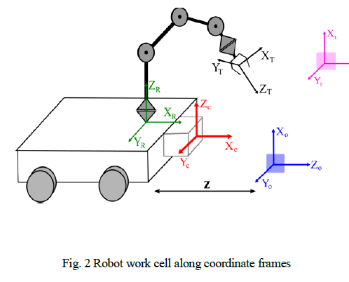 |
| XT, YT, ZT Tool reference frame |
| XR, YR, ZR Base reference frame |
| Xc, Yc, Zc Camera reference frame |
| Xt, Yt, Zt Target reference frame |
| B. Kinematics |
| Kinematics is the study of motion without regard to the force which causes it. From kinematics we can know the position, velocity and acceleration. The kinematics of manipulator involves the study of geometric and time based properties of the motion, and how various links of the manipulator moves with respect one another [13]. |
 |
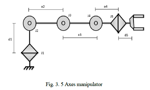 |
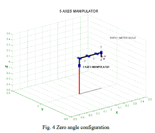
| Kinematic equations are solved and generated by using standard DH conventions with the help of Robotic Toolbox [2] [3] and it is plotted as shown in Fig. 4. |
 |
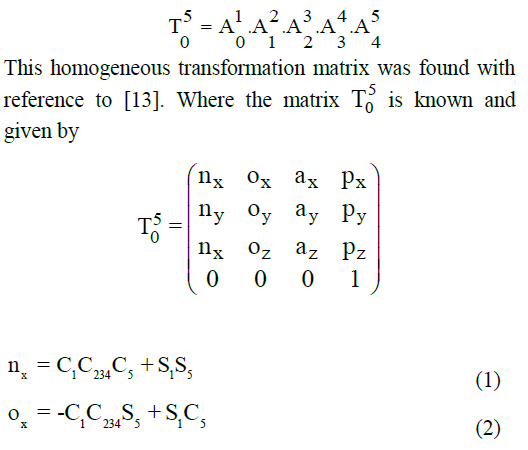
| A manipulator consists of a series of links connected by a series of joints. Let 1 0 A describe the position and orientation of the first link, 1 0 A describe the position and orientation of the second link, and so on with respect to the base coordinate frame. Then the position and orientation of the tool with respect to the base coordinate will be |
 |
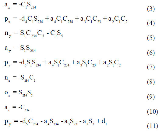 |
| Depending upon this set of known parameters from equation(1) to equation(11) of an object frame, joint angles are calculated. |
| C. Work Volume |
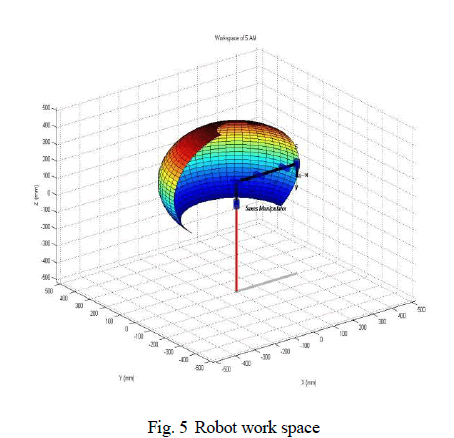
| The work volume is the spatial region within which the end of the robotâÃâ¬ÃŸs wrist can be manipulated. The work volume of an industrial robot is determined by its physical configuration, size, and the limits of its arm and joint manipulations. Here, the design of the manipulator does not limit the work volume. But, the actuator limits the work volume. |
| Work volume of the 5 axes manipulator was shown in Fig. 5. Because of its mobility, the workspace of this robot is infinite. |
 |
CONCLUSION |
| A mobile 5 axes manipulator was developed which is able to pick an object and place it in a target location by fusion of information from vision sensor and distance measuring sensor. The motion of a vehicle towards the object also visually controlled without tracking any predefined path. |
ACKNOWLEDGMENT |
| The authors greatly thankful to Mr.R.Senthilnathan, Assistant Professor, Department of Mechatronics, SRM University for his valuable suggestions and Mr. S. Gopinath, Junior research fellow of Bharath University Chennai for assisting in CAD modeling. |