ISSN ONLINE(2319-8753)PRINT(2347-6710)

All submissions of the EM system will be redirected to Online Manuscript Submission System. Authors are requested to submit articles directly to Online Manuscript Submission System of respective journal.

A Review on Routing Protocols for In-Network Aggregation in Wireless Sensor Networks

P.THIRUMOORTHY1 , DR.N.K.KARTHIKEYAN2, S.SUDHA3, B.MANIMEGALAI4
  1. Associate Professor, Department of Computer Science and Engineering. Nandha College of Technology1
  2. Professor and Head, Department of Information Technology, Sri Krishna College of Engineering and Technology Coimbatore, Tamilnadu
  3. P.G Scholars, Department of Computer Science and Engineering, Nandha College of Technology, Erode, Tamilnadu
Related article at Pubmed, Scholar Google

Visit for more related articles at International Journal of Innovative Research in Science, Engineering and Technology

Abstract

In this project, we can design data aggregation using the routing protocols, that can reduce the cost of communication in the wireless sensor network. Due to the multiple sensor nodes has detected one or more events, results in heavy traffic. To save the energy, the network should notify the event properly, only when an event occurs. Overhead occurs in InFRA because its scalability is very low. In The proposed DRINA (Data Routing for In-Network Aggregation) algorithm reduces the communication cost and saves the energy consumption by building the routing tree, maximized the number of overlapping routes and eliminating the redundant data. The performance of the DRINA has compared to two other known protocols: the Information Fusion-based Role Assignment (InFRA) and Shortest Path Tree (SPT) algorithms and Centered-At- Nearest-Source algorithm.

Keywords

Face detection, Gabor wavelet, feed forward neural network classifier, Multilayer perceptron

INTRODUCTION

Human face detection and recognition is an active area of research spanning several disciplines such as image processing, pattern recognition and computer vision. Face detection and recognition are preliminary steps to a wide range of applications such as personal identity verification, video-surveillance, lip trocking, facial expression extraction, gender classification, advanced human and computer interaction. Most methods are based on neural network approaches, feature extraction, Markov chain, skin color, and others are based on template matching [1]. Pattern localization and classification is the step, which is used to classify face and non- face patterns. Many systems dealing with object classification are based on skin color. In this paper we are interested by the design of an ANN algorithm in order to achieve image classification. This paper is organized as follows: In section II, we give an overview over classification for face detection. Description of our model is discussed in Section III. Section IV deals with the training method.

II. CLASSIFICATION FOR FACE DETECTION

While numerous methods have been proposed to detect face in a single image of intensity or color images. A related and important problem is how to evaluate the performance of the proposed detection methods [1]. Many recent face detection papers compare the performance of several methods, usually in terms of detection and false alarm rates. It is also worth noticing that many metrics have been adopted to evaluate algorithms, such as learning time, execution time, the number of samples required in training, and the ratio between detection rates and false alarms. Face detection can be viewed as two-class Recognition problem in which an image region is classified as being a “Face” or “nonFace”. Consequently, face detection is one of the few attempts to recognize from images a class of objects for which there is a great deal of within-class variability. Face detection also provide interesting challenges to the underlying pattern classification and learning techniques. The class of face and no face image are decidedly characterized by multimodal distribution function and effective decision boundaries are likely to be nonlinear in the image space. Pattern localization and classification are CPU time intensive being normally implemented in software, however with lower performance than custom implementations. Custom implementation in hardware allows real-time processing, having higher cost and time-to-market than software implementation. Some works [2,3,4] uses ANN for classification, and the system is implemented in software, resulting in a good performance (10 sec for localization and classification). A similar work is presented in [5], aiming to object localization and classification. We are interested in the implementation of an ANN algorithm& design of a Gabor filter in order to provide better image classification. The MLP (Multi-layer Perceptron) algorithm is used to classify face and non-face patterns before the recognition step.

III.MULTI-LAYERS PERCEPTRON

The MLP neural network [1] has feed forward architecture within input layer, a hidden layer, and an output layer. The input layer of this network has N units for an N dimensional input vector. The input units are fully connected to the I hidden layer units, which are in turn, connected to the J output layers units, where J is the number of output classes. A Multi-Layers Perceptron (MLP) is a particular of artificial neural network [7]. We will assume that we have access to a training dataset of l pairs (xi, yi) where x i is a vector containing the pattern, while yi is the class of the corresponding pattern. In our case a 2-class task, yi can be coded 1 and -1.
We considered a MLP (Multi-Layers Perceptron) with a 3 layers, the input layer is a vector constituted by n2 units of neurons (n x n pixel input images). The hidden layer has n neurons, and the output layer is a single neuron which is active to 1 if the face is presented and to otherwise. The activity of a particular neuron j in the hidden layer is written by
image
a sigmoid function.Where W1i is the set of weights of neuron i, b1(i) is the threshold and xi is an input of the neuron.Similarly the output layer activity is
image
In our system, the dimension of the retina is 27x18 pixels represent human faces and non-face, the input vector is constituted by 2160 neurons, the hidden layer has 100 neurons. We are designing a feed forward neural network with one hundred neurons in the hidden layer and one neuron in the output layer. Prepares images for training phase.
All data form both “face” and “non-face” folders will be gathered in a large cell array. Each column will represent the features of an image, which could be a face, or not.Rows are as follows :
Row 1: File name
Row 2: Desired output of the network corresponded to the feature vector.
Row 3: Prepared vector for the training phase
We will adjust the histogram of the image for better contrast. Then the image will be convolved with Gabor filters by multiplying the image by Gabor filters in frequency domain. . To save time they have been saved in frequency domain before Features is a cell array contains the result of the convolution of the image with each of the forty Gabor filters. These matrices have been concated to form a bif 135x144 matrix of complex numbers. We only need the magnitude of the result. That is why “abs” is used.135x144 has 10,400 pixels. It means that the input vector of the network would have 19,400 values, which means a large amount of computation. So we have reduced the matrix size to one-third of its original size by deleting some rows and columns. Deleting is not the best way but it save more time compare to other methods like PCA.We should optimize this function as possible as we can.
First training the neural network and then it will return the trained network. The examples were taken from the Internet database. The MLP will be trained on 500 face and 200 non-face examples.

IV. TRAINING METHODOLOGY

The MLP with the training algorithm of feed propagation is universal mappers, which can in theory, approximate any continuous decision region arbitrarily well. Yet the convergence of feed forward algorithms is still an open problem. It is well known that the time cost of feed forward training often exhibits a remarkable variability. It has been demonstrated that, in most cases, rapid restart method can prominently suppress the heavy-tailed nature of training instances and improve efficiency of computation. Multi-Layer Perceptron (MLP) with a feed forward learning algorithms was chosen for the proposed system because of its simplicity and its capability in supervised pattern matching. It has been successfully applied to many pattern classification problems [9]. Our problem has been considered to be suitable with the supervised rule since the pairs of input-output are available. For training the network, we used the classical feed forward algorithm. An example is picked from the training set, the output is computed.

V. ALGORITHM DEVELOPMENT AND RESULTS

VI. 2D GABOR WAVELET REPRESENTATION OF FACES

Since face recognition is not a difficult task for human beings, selection of biologically motivated Gabor filters is well suited to this problem. Gabor filters, modeling the responses of simple cells in the primary visual cortex, are simply plane waves restricted by a Gaussian envelope function [22].
An image can be represented by the Gabor wavelet transform allowing the description of both the spatial frequency structure and spatial relations. Convolving the image with complex Gabor filters with 5 spatial frequency (v = 0,…,4) and 8 orientation (μ = 0,…,7) captures the whole frequency spectrum, both amplitude and phase (Figure 5).
In Figure 6, an input face image and the amplitude of the Gabor filter responses are shown above.One of the techniques used in the literature for Gabor based face recognition is based on using the response of a grid representing the facial topography for coding the face. [23, 25, 26, 27].Instead of using the graph nodes, high-energized points can be used in comparisons which forms the basis of this work. This approach not only reduces computational complexity, but also improves the performance in the presence of occlusions.
A. Feature extraction
Feature extraction algorithm for the proposed method has two main steps in (Fig. 8): (1) Feature point localization,(2) Feature vector computation.
B. Feature point localization
In this step, feature vectors are extracted from points with high information content on the face image. In most featurebased methods, facial features are assumed to be the eyes, nose and mouth. However, we do not fix the locations and also the number of feature points in this work. The number of feature vectors and their locations can vary in order to better represent diverse facial characteristics of different faces, such as dimples, moles, etc., which are also the features that people might use for recognizing faces (Fig. 7).
From the responses of the face image to Gabor filters, peaks are found by searching the locations in a window W0 of size WxW by the following procedure:
A feature point is located at (x0, y0), if
image
image
where Rj is the response of the face image to the jth Gabor filter N1 N2 is the size of face peaks of the responses. In our experiments a 9x9 window is used to search feature points on Gabor filter responses. A feature map is constructed for the face by applying above process to each of 40 Gabor filters.
A. Feature vector generation
Feature vectors are generated at the feature Points as a composition of Gabor wavelet transform coefficients. kth feature vector of ith reference face is defined as,
image
While there are 40 Gabor filters, feature Vectors have 42 components. The first two components represent the location of that feature point by storing (x, y) coordinates. Since we have no other information about the locations of the feature vectors, the first two components of feature vectors are very important during matching (comparison) process. The remaining 40 components are the samples of the Gabor filter responses at that point. Although one may use some edge information for feature point selection, here it is important to construct feature vectors as the coefficients of Gabor wavelet transform. Feature vectors, as the samples of Gabor wavelet transform at feature points, allow representing both the spatial frequency structure and spatial relations of the local image region around the corresponding feature point.
1) First Section:
2) Second Section: In this section the algorithm will check all potential face-contained windows and the windows around them using neural network. The result will be the output of the neural network for checked regions.
3) Third Section:
This architecture was implemented using Matlab in a graphical environment allowing face detection in a database. It has been evaluated using the test data of 500 images containing faces, on this test set we obtained a good detection.

VII. CONCLUSION &FUTURE WORK

In this paper, a new approach to face detection with Gabor wavelets& feed forward neural network is presented. The method uses Gabor wavelet transform & feed forward neural network for both finding feature points and extracting feature vectors. From the experimental results, it is seen that proposed method achieves better results compared to the graph matching and eigenface methods, which are known to be the most successive algorithms. In the proposed algorithm, since the facial features are compared locally, instead of using a general structure, it allows us to make a decision from the parts of the face. For example, when there are sunglasses, the algorithm compares faces in terms of mouth, nose and any other features rather than eyes. Moreover, having a simple matching procedure and low computational cost proposed method is faster than elastic graph matching methods. Proposed method is also robust to illumination changes as a property of Gabor wavelets, which is the main problem with the eigenface approaches. A new facial image can also be simply added by attaching new feature vectors to reference gallery while such an operation might be quite time consuming for systems that need training. Although detection performance of the proposed method is satisfactory by any means, in future it would be further improved with some small modifications and/or additional preprocessing of face images. Such improvements can be summarized as;
1) A set of weights can be assigned to these feature points by counting the total times of a feature point occurs at those responses.
2) When there is a video sequence as the input to the system, a frame giving the “most frontal” pose of a person should be selected to increase the performance of face detection algorithm.
3) In order to further speed up the algorithm, number of Gabor filters could be decreased with an acceptable level of decrease in detection performance.

Figures at a glance

Figure 1 Figure 2a Figure 2b Figure 2c Figure 5


Figure 6 Figure 7 Figure 8 Figure 9 Figure 10.1


Figure 10.2 Figure 10.2 Figure 10.4 Figure 10.5 Figure 10.6
Figure 10.2 Figure 10.3 Figure 10.4 Figure 10.5 Figure 10.6


Figure 10.7
Figure 10.7
 

References

Keywords

Routing protocol, in-network aggregation, wireless sensor networks, InFRA\

INTRODUCTION

A Wireless Sensor Network (WSN) is built of nodes from a few to several hundreds or even thousands of nodes where each node is connected to one sensor. Each such sensor node has several parts radio transceiver, microcontroller and battery. Depending on the complexity of the individual sensor nodes, the cost of the sensor nodes ranging from few to hundreds of dollars. Forest-fire detection, water quality monitoring and natural disaster prevention are some of the applications of wireless sensor networks. Routing plays an important role in data aggregation. It is the process of selecting paths in network traffic. Routing schemes has different delivery semantics: unicast, multicast, broadcast, any cast and geocast. One of the main challenges in routing algorithms is even in the presence of nodes failures and interruptions in communications, how guarantee the sensed data is delivered. Because of the higher redundancy in raw data collected by sensor nodes, in-network aggregation make used to decrease the communication cost by forwarding a little aggregated information and eliminating redundancy. To overcome these challenges, we propose Data Routing algorithm for In-Network Aggregation for WSNs, which we refer to as DRINA algorithm. This algorithm will maximize the information fusion in reliable way by fault tolerant mechanism. This paper is organized as follows: in Section 2, discussion about Centered-At-Nearest-Source algorithm. Section 3 some theoretical description about SPT and InFRA. In Section 4 introduces our proposed DRINA algorithm and Finally, Section 5 presents our conclusions and Future work.

II.CENTERED–AT- NEAREST – ALGORITHM

In this technique,the node which is closest to the sink node could act as an aggregation point. This node gathered the data from all other source node and then forwards this aggregated data towards the sink. when the number of sources are high,then it results in a poor performance because many sources may directly route towards the sink faster rather than the node that route towards one particular node that is nearest to the sink.
image
It construct the routing tree in a distributed fashion. Whenever an event is detected by every node, by using the shortest path it reports the gathered information to the sink node. whenever this shortest path overlap for different sources, information fusion occurs. In the Fig. 1, consist of non overlapping routes because simple shortest path is used. Fusion does not takes place between cluster data.Distance vector routing and link state vector routing are the protocols to calculate the shortest path. In the distance vector routing, each router sends a vector of distances to its neighbor node. The vector contains distances to all nodes. In the link state routing, each router sends a vector of distances to all nodes. The vector contains distances to the neighbor node.
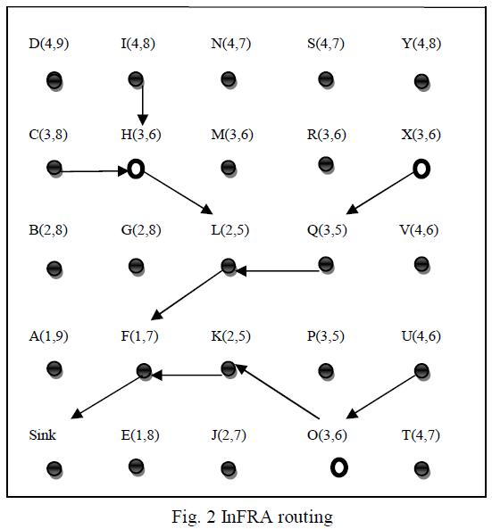
Information-Fusion-based Role Assignment,in this algorithm two or more nodes detect the same event then the nodes are grouped into clusters. Cluster head collects the data from its members and forward the event data to the sink.In the Fig. 2, minimum shortest path is found. The nodes H,O and x has performed Inter-cluster fusion.
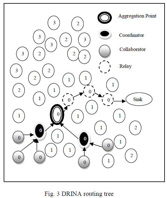
The following roles are involved to create the routing infrastructure:
image
 Collaborator (Cluster Member): An event is detected and forward its collected data to a coordinator node.
 Coordinator (Cluster Head): An event is detected and also responsible for gathering data from the collaborator and performs aggregation and sends the result to a sink node.
 Sink :A node that receiving data from a set of collaborator and coordinator nodes.
 Relay :A node receives data from another node and forwards towards the sink.
When there is no event is detected then except the sink, all the sensor node performs relay role.
image

A .Cluster Formation

Each event involves in sensor networkhas detected by only one cluster called Head, and nodes are detected by cluster members.We have several strategies to select the cluster head(Coordinator).We can select the node which has the smallest id,node which is very closest to the sink node, highest degree,less energy consumption.

B. Route Formation

Route are constructed by choosing the best neighbor at each hop.Depending on the followingconstraints,the best neighbor node can be chosen.The node which is Shortest path to the sink. If two or more nodes closest to the sink ,then tie appears. In that cases we choose the node which has shortest distance to other coordinator(Cluster Head).Aggregated coordinatorsdistance could taken into this consideration.
image
Where distance(vi, u) is the distance between nodes vi and u , in hops.Coordset is the set of all coordinator nodes. To understand this,as soon as the cluster get formed each coordinator floods a control message,during this floodingevery node computes its distance to that coordinator. Therefore chances of route overlapping and data aggregation are enhanced.

C. Information fusion

In this InFRA algorithm,we have two types of information fusion intra-cluster, inter-cluster fusion. In the former the tree is composed only of collaborators(i ,e) only data from the collaborator nodes are fused whereas in the later, it allows the aggregation of multiple clusters (i,e) only data from the coordinator nodes are fused.

D.Dynamic Topologies

In this algorithm dynamic topologies are illustrated.while notifying an event,if the chosenrelay node get fails, then a new relay node(second best option) is chosen. If the failure rate is high, then the InFRA algorithm can’t find the best path. Proactive solutions are the best choice based on the failure rate.

IV. DRINA (DATA ROUTING FOR IN-NETWORK AGGREGATION)

While maximizing data aggregationDRINA algorithm is to construct the routing tree from source to the sink node with the shortest path. This algorithm has three phases.

A .Constructing the Hop Tree

Hop tree is constructed from sensor node to the sink node. The distance is computed inhops from the sink node to each node in the network. The sink node sends HCM(Hop Configuration Message) to allnodes through flooding. Thisand HopToTree which is the distance through which theHCM message has passed.The initial value of HopToTreeis 1 at the sink.This HCM message is passed to its neighbors. when receiving this message, each node verifies if the stored HopToTree value is greater than the value of HopToTree in the received HCM message.If the condition is true then the node update the stored HopToTree value with the value in the HCM message else the node discards the received HCM message.

B. Formation of cluster

Similar to InFRA,Election algorithm should be done when one or more nodes detects the same event. Basedon the result of this algorithm, roles are assigned to the
image
The advantage of this algorithm is that the information collected by the nodes which are sensing the same event will be aggregated at a point (called aggregation point) is more efficient.

C.HopTree Updates

New route is established by the coordinator for the event dissemination. To establish the route(Fig. 3),Coordinator sends a route establishment message to its NextHop node.Whenthis node receives a route establishment message,it retransmits the message to its NextHop and starts updating node is reached or a node that is closer to the already established route.
After the route establishment,hoptree updating process is started.The main aim of this phase is to update the value of the HopToTree in all nodes so that newly established route can taken into consideration.Relay nodes are responsible for this process.Each node will send only one packet so that the whole cost of this process is same as flooding.

D. Route Repair Mechanism

DRINA algorithm has piggybacked and ACKbased route repair mechanism.when the relay node wants to forward data to its NextHop node then it sends the data packet. For every data packet transmission,it sets the timeout and waits for acknowledgement.If the node has not receive any acknowledgement then it recognize that particular node get failed and select the new node.A newly partial reconstructed path is created after the repairing mechanism is applied.

V.CONCLUSION AND FUTURE WORK

In this paper, DRINA(Data Routing for In- Network Aggregation) algorithm are compared to SPT, CNS and InFRA with respect to stability, communication cost, aggregation rate, data delivery data. Table I shows the comparison ofthe above algorithm.DRINA improves the delivery rate thanInFRA ,SPT and CNS by performing the fault tolerant mechanism and maximizing the aggregation points. DRINA performs efficient only in the case of staticevents of fixed radius.Our future work may consider the Dynamic sizes of events.

References

  1. I.F. Akyildiz, W. Su, Y. Sankarasubramaniam, and E. Cyirci, “Wireless Sensor Networks: A Survey,” Computer Networks, vol. 38, no. 4, pp. 393-422, Mar. 2002
  2. G. Anastasi, M. Conti, M. Francesco, and A. Passarella, “Energy Conservation in Wireless Sensor Networks: A Survey,” Ad Hoc Networks, vol. 7, no. 3, pp. 537-568, http://dx.doi.org/10.1016/j.adhoc.2008.06.003, May 2009.
  3. A. Boukerche, R.B. Araujo, and L. Villas, “Optimal Route Selection for Highly Dynamic Wireless Sensor and Actor NetworkEnvironment,” Proc. 10th ACM Symp. Modeling, Analysis, andSimulation of Wireless and Mobile Systems (MSWiM ’07), pp. 21-27,2007
  4. H.S. AbdelSalam and S. Olariu, “A Lightweight Skeleton Construction Algorithm for Self-Organizing Sensor Networks,” Proc. IEEE Int’l Conf. Comm. (ICC), pp. 1-5, http://dblp.unitrier. de/db/conf/icc/icc2009.html#AbdelSalamO09, 2009.
  5. L. Villas, A. Boukerche, R.B. de Araujo, and A.A.F. Loureiro, “Highly Dynamic Routing Protocol for Data Aggregation in Sensor Networks,” Proc. IEEE Symp. Computers and Comm (ISCC),pp.496502,http://dx.doi.org/10.1109/ISCC.2010.5546580, 2010.
  6. I. Chatzigiannakis, T. Dimitriou, S.E. Nikoletseas, and P.G. Spirakis, “A Probabilistic Algorithm for Efficient and Robust Data Propagation in Wireless Sensor Networks,” Ad Hoc Networks, vol. 4, no. 5, pp. 621-635, 2006.
  7. L.A. Villas, D.LGuidoni, R.B. Arau´ jo,A. Boukerche, and A.A. Loureiro, “A Scalable and Dynamic Data Aggregation ware Routing Protocol for Wireless Sensor Networks,” Proc. 13th AC Int’l Conf. Modeling, Analysis, and Simulation ofWireless and MobileSystems, pp. 110-117
  8. E.F. Nakamura, A.A.F. Loureiro, and A.C. Frery, “Information Fusion for Wireless Sensor Networks: Methods, Models, and Classifications,” ACM Computing Surveys, vol. 39, no. 3, pp. 9- 1/9-55, 2007.
  9. F. Hu, X. Cao, and C. May, “Optimized Scheduling for Data Aggregation in Wireless Sensor Networks,” Proc. Int’l Conf. Information Technology: Coding and Computing (ITCC ’05), pp. 557- 561, 2005.
  10. I. Solis and K. Obraczka, “The Impact of Timing in Data Aggregation for Sensor Networks,” IEEE Int’l Conf. Comm., vol. 6, pp. 3640-3645, June 2004.
  11. B. Krishnamachari, D. Estrin, and S.B. Wicker, “The Impact of Data Aggregation in Wireless Sensor Networks,” Proc. 22nd Int’l Conf. Distributed Computing Systems (ICDCSW ’02), pp. 575- 578,2002.
  12. J. Al-Karaki, R. Ul-Mustafa, and A. Kamal, “Data Aggregation inWireless Sensor Networks—Exact and Approximate Algorithms,”Proc. High Performance Switching and Routing Workshop (HPSR ’04),pp. 241-245, 2004.
  13. J. Al-Karaki and A. Kamal, “Routing Techniques in Wireless Sensor Networks: A Survey,” IEEE Wireless Comm., vol. 11, no. 6,pp. 6-28, Dec. 2004.
  14. E. Fasolo, M. Rossi, J. Widmer, and M. Zorzi, “In-network Aggregation Techniques for Wireless Sensor Networks: A Survey,” IEEE Wireless Comm., vol. 14, no. 2, pp. 70-87, Apr. 2007.
  15. C. Intanagonwiwat, R. Govindan, D. Estrin, J. Heidemann, and F. Silva, “Directed Diffusion for Wireless Sensor Networking,” IEEE/ACM Trans. Networking, vol. 11, no. 1, pp. 2-16, Feb. 2003.
  16. E.F. Nakamura, H.A.B.F. de Oliveira, L.F. Pontello, and A.A.F. Loureiro, “On Demand Role Assignment for Event- Detection in Sensor Networks,” Proc. IEEE 11th Symp.Computers and Comm.(ISCC ’06), pp. 941-947, 2006.
  17. A.P. Chandrakasan, A.C. Smith, and W.B. Heinzelman, “An Application-Specific Protocol Architecture for Wireless MicrosensorNetworks,” IEEE Trans. Wireless Comm., vol. 1, no. 4, pp. 660-670, Oct. 2002.