ISSN ONLINE(2319-8753)PRINT(2347-6710)
ISSN ONLINE(2319-8753)PRINT(2347-6710)
Sanjeet Tawade1, Akash Suryavanshi2
|
| Related article at Pubmed, Scholar Google |
Visit for more related articles at International Journal of Innovative Research in Science, Engineering and Technology
A stresses are generated due to temperature fluctuations in regions where cold and hot flows are intensively mixed together. Such situation of mixing appears in turbulent flow through a junction in pipe Tee. Fluctuating stresses imposed on a system are potential causes of thermal fatigue failures in energy cooling systems of a plant. The turbulent mixing in a junction is investigated by a coupled approach of fluid-flow calculations and mechanical calculations. Whenever there is a significant exchange of energy between a moving fluid and a solid structure the widely use of Fluid-Structure Interaction (FSI) analysis is done. Therefore, in this study thermal fatigue evaluation of flowing system at mixing junction is performed using the Fluid-Structure Interaction (FSI) analysis. Using thermal hydraulic analysis, temperature distributions at different zone are determined and their results are applied to the structural model of the piping system to determine the thermal stress.
Keywords |
| Fluid Structure Interaction, Computational Fluid Dynamics, Thermal fatigue, Structural Analysis. |
INTRODUCTION |
| In real life many problems deals with the interaction of fluids with the structure as well as in some cases vice versa. Pressure pulsation and thermal loads always creates excessive noise as well as may lead to damage machinery. Due to valuable analysis capabilities that are now available for many practical cases of fluid flow in Mechanical Engineering the trend will undoubtedly grow stronger, thanks to a newly emerging field of analysis. The three multismultiscale, multiphysics and multiprocessing. Collectively these trends lead to the formulation and model-based simulation of coupled systems: systems whose behaviour is driven by the interaction of functionally distinct components. In Multiphysics new field of analysis is the fully coupled solution of Fluid Flows with Structural Interactions, commonly used as Fluid-Structure Interaction (FSI). In past fluid mixing area is a well-known phenomenon that has already been studied. Generally, this phenomenon is linked to turbulent mixing of two fluids at two different temperatures and creates elephant skin type damage at the inner surface of the component and some cracks, which are small, compared to the thickness of the pipe structure. |
| Tee Junction: There are lots of T-junction-type components in which fluids meet at different temperatures in cooling system of nuclear reactor. These components, occurrence of fractures due to thermal mixing leads. In the case of thermal mixing in T-junction, hydraulic design (i.e. dimensions and momentum ratios) of tee components is important. The thermal load magnitude and intensity are directly affected by the momentum ratio of hot and cold streams. Fig. 1 |
 |
| Fluid-Structure Interaction (FSI): Fluid-Structure Interaction (FSI) analysis is an example of a multiphysics problem where the interaction between two different analyses is taken into account. The FSI analysis in the Mechanical application involves performing a structural or thermal analysis in the Mechanical application taking into account the interaction with the corresponding fluid or previous CFD analysis. The interaction between the two analyses typically takes place at the boundary of the Mechanical application model - the fluid-structure interface, where the results of one analysis is passed to the other analysis as a load. A structural stress analysis can also be performed in the Mechanical application by transferring temperatures across solid bodies from a previous. The FSI analysis can be one-way or twoway depending upon the interaction of the two system coupling. Here we are going to study one-way FSI coupling. |
| Procedure for the Analysis: The steps flow for one-way FSI scheme is applied to evaluate the thermal analysis in piping using analysis software. |
| 3D Modeling: Model of Tee junction pipe and fluid flowing through pipe can be created in Modelling software. Use of different feature, the geometry will be created as per the required dimension. The model should have two bodies one the solid body that the pipe and second body that is the fluid flowing through the pipe. |
| Meshing: Geometry transfer or import from Model software to Meshing software. Here the mesh will be done. This meshing process is nothing but discretization of model for numerical analysis. 3D element mesh will be created on Tee junction pipe and fluid body. CFD meshing will be done and the node/element connectivity between solid and fluid bodies should be taken care to get good results. Mesh quality and size can be maintained by using different meshing algorithms which will influence to get better result from the solver. |
| Fluid Flow Analysis: Fluid body along with Mesh will be transfer in CFD software. CFD constrain like temperature velocity at both the inlets will be applied. Respective setting required to solve the tee mix will be take care and then solved for transient analysis. For any accurate CFD analysis of thermal fatigue, it is very important that the thermal fluctuations on the walls of the mixing tee are accurately predicted. Based on the temperature transient in the pipe wall obtained by the CFD simulation, thermal stress will be calculated. |
| Structural Analysis: Model created in modelling software will transfer only pipe geometry in Structural Analysis. The pipe will be mesh using structural mesh. The CFD thermal result of pipe will be transfer to pipe geometry through FSI analysis mapping of nodes and elements. The CFD thermal reports will be directly imported and will be applied on pipe body. Structural constrain will be applied on the geometry and respective stress will be calculated. |
II. LITERATURE SURVEY |
| Masayuki Kamaya et al. [6] worked for the simulation target that was an experiment for a mixing pipe tee at junction, in which cold water flowed into the main pipe from a branch pipe at tee junction. The flow of cold water along the main pipe wall and caused a cold spot, at the membrane stress was relatively large observed. Based on the analysed thermal stress in the pipe, the magnitude of the fatigue damage was assessed to the linear damage accumulation rule and the rain-flow procedure. |
 |
| Accurate distributions of the thermal stress and fatigue damage could be recognized. Large axial stress occurred downstream from the branch pipe due to the cold spot. The critical area was found at the junction of the pipe as shown in the Fig. 2(a).And the zoom image of the critical area is shown in Fig. 2(b). The position of the cold spot changed slowly in the circumferential direction, and was found the main cause of the fatigue damage. |
| The fatigue damage was observed for various differences in the temperature between the both main and branch pipes at the junction. The magnitude of accumulated damage increased rapidly when the temperature difference exceeded the value of fatigue limit, it was recommended that the stress amplitude should be suppressed less than the fatigue limit. The Fig. 3.shows the mean stress obtained by taking the time averaged value at each element. The maximum stress was much larger for the axial stress than the circumferential stress. |
 |
| For the Thermal stress for fatigue damage, the change in the circumferential and axial stresses were maximum damage factor, for the maximum variation range and the maximum stress. The points of the maximum variation range were not the same as those of the maximum damage factor, although fluctuation of the stress was significant at both points. The axial stress distribution when the axial stress became a maximum or minimum at the point of the maximum damage factor. The point of the maximum damage factor was located near the edge of the cold spot, and was included in the cold spot when the stress was the maximum, while it was outside the cold spot when the stress was the minimum. The flow of cold water was deflected by the main flow and flowed along the symmetry line, and swayed downstream from the branch pipe. This caused the fluctuation of the cold spot shape. The boundary of the cold spot fluctuated in the circumferential direction across the point of the maximum damage factor. |
| HuseyinAyhan et al. [2] carried a turbulent mixing of fluids at different temperatures can lead to temperature fluctuations at the pipe junction and pipe material. These fluctuations, inducing cyclical thermal stresses and resulting thermal fatigue, can cause unexpected failure of pipe material. Therefore, accurate characterization of temperature fluctuations is important in order to estimate the life of the pipe and lifetime of pipe material. Thermal fatigue of coolant circuits of nuclear power plants is one of the major issues in nuclear safety now a day. To investigate this thermal fatigue damage, the OECD/NEA has recently organized a benchmark study including some of results of present work for prediction of temperature and velocity fluctuations performing a thermal mixing experiment in a pipe tee junction. In CFD study of turbulent thermal mixing of two water streams having different temperatures in a pipe tee junction was performed and compared with the experimental results that they received. The large-eddy simulation (LES) computations with an eddy viscosity type SGS model resulted in adequately accurate predictions of temperature and velocity fluctuations which are important in order to characterize thermal fatigue whereas, as expected, the results of Reynolds averaged Navier–Stokes (RANS) computations, steady or unsteady, failed to provide accurate results. The huge amount of computational time required by the large-eddy simulation LES computations may be reduced considerably by employing the NITA scheme which also allows a longer flow time to be simulated enabling more accurate predictions of the statistics of the temperature and velocity fluctuations. It was found that the magnitude of thermal cyclical stress depends on temperature difference of the two fluids. The thermal striping becomes considerably important when temperature difference of both the fluids is high. The final results provide information about the lifetime of mixing pipe tees exposed to thermal loads. There are several useful findings about the prediction of thermal load, the thermal mixing phenomenon is still a challenging issue for the nuclear technology due to the computation time, money and CPU requirements. Their aim was to estimate the frequency of velocity and temperature fluctuations in the mixing pipe region using Computational Fluid Dynamics. The Reynolds Averaged Navier-Stokes and Large Eddy Simulation models were used to simulate the turbulence. The Computational Fluid Dynamics results were compared with the experimental results which were available. The predicted large-eddy simulation LES results, even in coarse mesh form, were found to be in well agreement with the experimental results in terms of amplitude and the frequency of temperature and velocity fluctuations. |
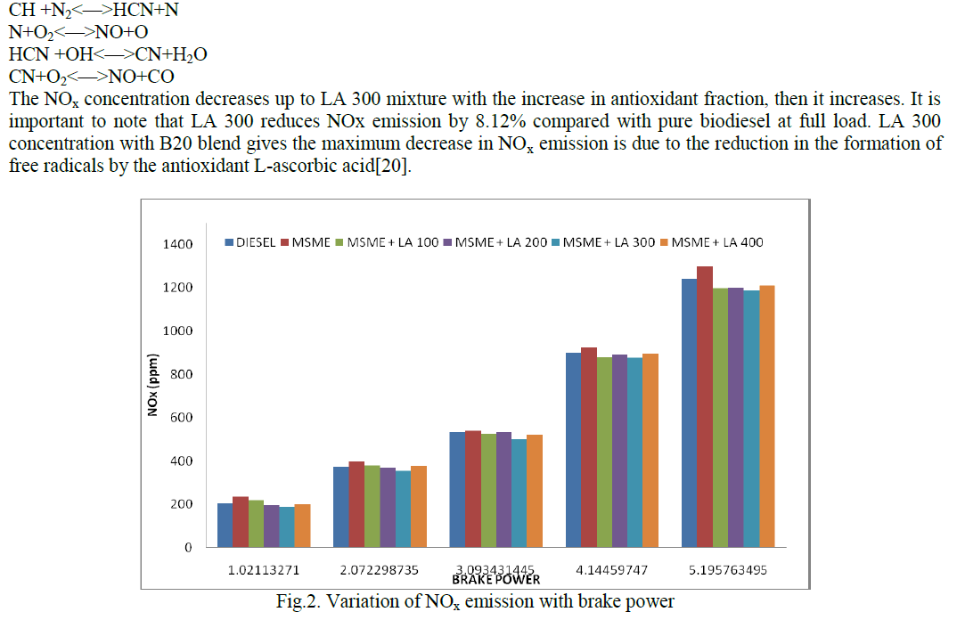
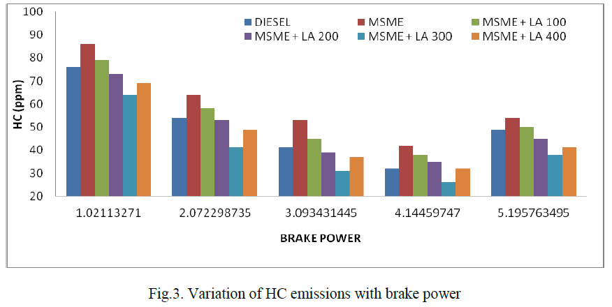
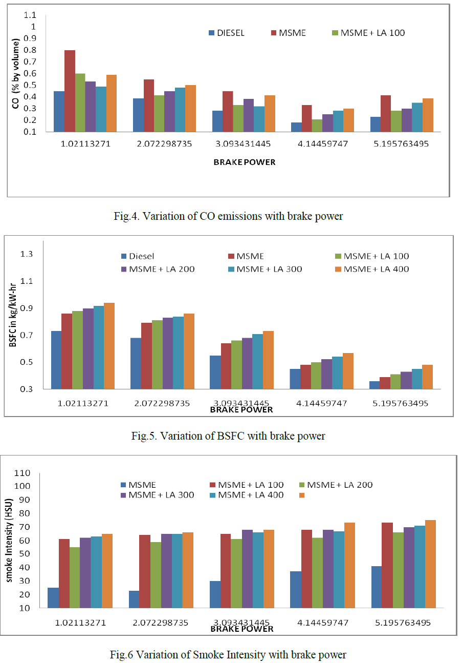
| Antti Timperi[1] studied that effect of mesh and flow velocity the contour plots of root-mean-squared temperature are shown at the pipe inner surface in Fig. 4 for the different meshes and flow velocities. The results for the different cases appear quite similar. The highest wall temperature fluctuations are found at the sharp corner of the Tee junction and at the main pipe right after the Tee junction. When the flow velocity is lower, somewhat higher wall temperature fluctuations are obtained near the corner. |
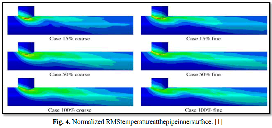 |
| On the other hand, with higher flow velocity the wall temperature fluctuation intensity spreads longer along the main pipe. Interestingly, even for Case 100% the root-mean-squared temperature distributions with the coarse and fine meshes are quite similar, although for this flow case the near-wall density of the coarse mesh is clearly insufficient. For studying also conjugate heat transfer between the fluid and the pipe wall, the plexi glass pipe of the experiment was replaced with a stainless steel one in the simulations. Comparison of steady and turbulent in lets showed that these have generally small effect in the bulk of the flow, while the effects are non-negligible near the walls, especially near the Tee junction where the highest temperature fluctuations were obtained. The turbulent in lets resulted generally in lower temperature fluctuations at the pipe inner surface. The mean and fluctuating components of velocity and temperature and the temperature spectra were over all in good agreement with the experiment with the both inlets when using the fine mesh. The turbulent inlets resulted unexpectedly in worse predictions of temperature fluctuations at two locations compared to the steady inlets. LES calculations have tendency for over-predicting the root-mean-squared temperatures at the two locations. The unexpected result with the turbulent in lets may have been caused by insufficient mesh resolution. The relatively high molecular Prandtl number led to more strict mesh requirement for temperature than for velocity and increased importance of the sub-grid scale heat flux modeling. Therefore, it might be of interest to try to determine the turbulent Prandtl number more accurately, e.g. by using a dynamic sub-grid scale model, or to examine more advanced sub-grid scale heat flux models than the simple gradient diffusion one. Comparison of adiabatic and conjugate heat transfer (walls showed that the wall boundary condition has practically no effect in the logarithmic layer and upward, whereas at the wall surface the difference becomes significant. In the conjugate heat transfer case, the wall surface temperature fluctuations were considerably damped due to thermal inertia of the pipe wall.The normalized profiles and spectra for different flow velocities were quite similar and in good agreement with the measurements when using the fine mesh. This shows the suit ability of large-eddy simulation (LES) for modeling the mixing phenomenon, as found earlier also by others. With the coarse mesh, in general qualitative agreement with the experiment was found, but significant differences occurred in cross-stream mean velocity in the bulk of the flow and in Reynolds stresses near walls. The root-mean-squared temperatures at the pipe inner surface with the coarse and fine meshes were fairly similar, although the near-wall resolution of the coarse mesh was poor for the higher velocities. Studies of the heat transfer coefficient and fatigue life- time, performed, shows that compared to the fine mesh the coarse mesh yields nonconservative values for these quantities. With a lower velocity, somewhat higher wall temperature fluctuations were obtained near the Tee junction, whereas with a higher velocity the wall temperature fluctuations spread longer along the main pipe.Although the normalized distributions of various quantities were qualitatively similar for different velocities, some quantitative differences were found. |
| Hüseyin Ayhan1et al. [3] carried an experimental setup to test the analysis and found that the Thermal fatigue damage may occur when incompletely mixed hot and cold fluid streams reach the wall. Experimental and computational studies found that the most probable distance of thermal fatigue is two main pipe diameters at downstream after mixing. They had several test cases are simulated by Computational Fluid Dynamics code using Large Eddy Simulation turbulence model. Different branch pipe diameter and same flow rate conditions were consider for calculations of their effects on frequency and magnitude of temperature fluctuations are verified. For temperature fluctuations it is clearly seen in their analysis that branch duct hydraulic diameter increase, the length required to reach the thermal equilibrium increases. And while branch duct hydraulic diameter decreases, all the normalized temperatures at different points come closer to the theoretical value. Since hot stream flow rate is constant, flow velocity decreases when the branch duct hydraulic diameter increases. Rapid mixing takes place due to velocity of branch duct increase which cause heat transfer area to increase. For velocity fluctuations the branch duct hydraulic diameter decreases, the fully developed condition which exist before the junction, are disturbed considerably after the junction. As branch duct hydraulic diameter decreases, the length required reaching the hydraulic equilibrium increases. Fig. 5,presents mean centreline velocity distributions for three cases. In Fig. 5, in the case of Db/Dm = 0.857, velocity profile is similar to fully developed velocity profile. |
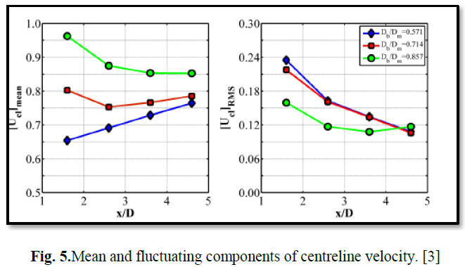 |
| A CFD study of turbulent thermal mixing of two water streams having different temperatures in a T-junction was performed for three different cases. Mass flow rate of main and branch duct inlet is constant for all cases however, momentum ratios are different. The temperature and velocity fluctuations, which have important characterizing thermal mixing, were observed by using LES turbulence model. The temperature and velocity data give information about magnitude and intensity of thermal load and the length required to reach the thermal and hydraulic equilibrium. |
| Yong-Jun Oh et al. [9]The low-cycle fatigue properties of a stabilized grade, type 347N austenitic stainless steels, and a un-stabilized grade, type 316N austenitic stainless steels, of containing approximately 0.1 mass% nitrogen were evaluated at ambient temperature and at the operating temperature of a nuclear power plant 330 degC . The type 347N exhibited a shorter fatigue life than type 316N. The difference found in the fatigue lives of the two grades of austenitic stainless steel was greater at ambient temperature than at 330 degC. The inferior low-cycle fatigue LCF resistance of type 347N compared to that of type 316N was largely attributed to the presence of carbonitride particles in type 347N, which showed a bimodal size distribution. Fine particles brought strong secondary cyclic hardening by holding dislocation cell walls at ambient temperature, whereas no secondary hardening happened at 330 degC. The hardening produced a higher stress concentration at the tip of the fatigue crack at constant strain amplitude, which caused in a lower fatigue life of the material at ambient temperature. Coarse particles performed as material defects that declined the fatigue resistance by creating voids on the surface of the propagating fatigue crack, regardless of the testing temperature. A study of the outer surface showed that the two types of steel exhibited different crack initiation modes on the surface. The study shows that in type 316N, the crack initiation mode was predominantly inter-granular at a high strain amplitude but trans-granular at lower strain amplitude. The study shows that in type 347N, the crack initiation mode was always inter-granular, irrespective of the strain amplitude. |
| In the Fig. 6 (a), depicts the plot of the total strain range versus the number of cycles to failure. The number of cycles to failure was defined as the number of cycles at which the load dropped to 80% of the saturated value. At the same experimental testing temperature, the fatigue life of type 347N was shorter than that of type 316N. An increase in experimental testing temperature decreased the fatigue life of the two austenitic stainless steels grades, which is general behaviour of austenitic stainless steels. It should also be noted that the temperature effect on low-cycle fatigue resistance is less significant in type 347N than in type 316N, as shown in Fig. 6 (b). It means when compared to type 316N, the low-cycle fatigue resistance of type 347N is inferior, and difference found is more distinctive at ambient temperature than at 330 degC. |
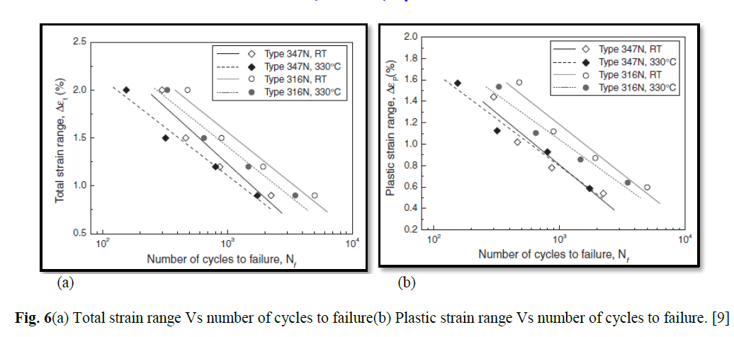 |
| The low-cycle fatigue resistance of type 347N stainless steel that was stabilized with niobium was compared with that of un-stabilized type 316N stainless steel at ambient temperature and at 330 degC. At both the temperatures, type 347N exhibited a shorter fatigue life than type 316N. In type 347N, the fatigue life at ambient temperature was short enough to be similar to that at 330 degC, whereas in type 316N, the lower test temperature resulted in a longer fatigue life. Such behaviours in type 347N were attributed to the niobium carbon-nitride precipitates that have a bimodal size distribution. The fine particles found induced strong secondary cyclic hardening at ambient temperature by pinning dislocation cell walls, while no secondary hardening occurred at 330 degC. The hardening produced a higher stress concentration at the tip of the fatigue crack at a constant strain amplitude and resulted in a shorter fatigue life at ambient temperature. The coarse particles found as material defects, reducing fatigue life by forming voids regardless of the testing temperature. After studying the outer surfaces, it was found that the two steel grades showed different surface crack initiation modes: for type 316N, it was predominantly inter-granular at a high strain amplitude but transgranular at a low strain amplitude; and for type 347N, it was always inter-granular, regardless of the strain amplitude. |
III. CONCLUSION |
| Temperature and its fluctuation intensity fields depended on the flow patterns. The different numerical simulations on challenging three-dimensional problems have illustrated the numerical efficiency of these procedures. Time averaged profiles of the transport scalar as well as profiles of the axial velocity where obtained in a wide 3D domain downstream of the Tee junction. The Equivalent stress analysis, the response characteristics of the T-junction subjected to the mixing flowage investigated, and found maximum at the joint contact. Spectral information was extracted in a frequency range where temperature measurements, traditionally used in T-junction mixing tests, fail due to the limited time resolution of thermo-sensors. This is ideal data material to check accuracy of transient CFD simulations like URANS and LES. In type 316N, the lower test temperature resulted in a longer fatigue life whereas 347N, the fatigue life at ambient temperature was short enough. |
References |
|