International Journal of Innovative Research in Science, Engineering and Technology
ISSN ONLINE(2319-8753)PRINT(2347-6710)
ISSN ONLINE(2319-8753)PRINT(2347-6710)
Karun Mani1, Nigee.K2
|
| Related article at Pubmed, Scholar Google |
Visit for more related articles at International Journal of Innovative Research in Science, Engineering and Technology
Ground improvement is an important requirement in today’s construction industry as land reclamation is becoming increasingly popular. The stone column technique is a very efficient method of improving the strength parameters of soil like bearing capacity and reducing consolidation settlement. It offers a much economical and sustainable alternative to piling and deep foundation solutions. Ground improvement when implemented through stone column technique aids in a much stable solution to construction in weak cohesive soils. The paper is an attempt to discuss in detail about this technique to improve soil stability, including it’s salient features, design parameters, major functions and drawbacks.
Keywords |
| Vibrofloat, Reclamation, Stabilization, Soil |
I. INTRODUCTION |
| India has large coastline exceeding 6000kms. In view of the developments on coastal areas in the recent past, large number of ports and industries are being built. In addition, the availability of land for the development of commercial, housing, industrial and transportation, infrastructure etc. are scarce particularly in urban areas. This necessitated the use of land, which has weak strata, wherein the geotechnical engineers are challenged by presence of different problematic soils with varied engineering characteristics. Many of these areas are covered with thick soft marine clay deposit, with very low shear strength and high compressibility. Out of several techniques available for improving the weak strata, stone columns have been used to a large extend for several applications. The design of stone column is still empirical, based on past experience and needs field trials before execution [4]. Stone columns are continuing to gain popularity today due to the considerable savings to cost and programme schedule that it can offer over conventional piling solutions in many circumstances [2] |
 |
II. INFLUENCING FACTORS |
| A. Soil |
| Subsurface soils whose undrained shear strength range from 7 to 50 kPa or loose sandy soils including silty or clayey sands represent a potential class of soils requiring improvement by stone columns. Subsurface conditions for which stone columns are in general not suited include sensitive clays and silts (sensitivity > 4) which lose strength when vibrated and also where suitable bearing strata for resting the toe of the column is not available under the weak strata. |
| B. Treatment depth |
| The treatment depth with stone column for a given soil profile should be so determined that the stone columns extend through the most significant compressible strata that contribute to the settlement of the foundation. Average depth of stone column accomplished in India may be around 15m, although with equipment modification, higher depths beyond 20 m are now becoming widespread. |
| C. Area of treatment |
| Stone columns work most effectively when used for large area stabilization of the soil mass. Their application in small groups beneath building foundations is limited and is not being used. Thus, large loaded areas which apply uniform loading on foundation soils, such as beneath embankments, tank farms and fills represent a major area of application. |
III. PRINCIPLE |
| The stabilization of soils by displacing the soil radially, with the help of a deep vibrator, refilling the resulting space with granular material and compacting the same with the vibrator is called vibrostone columns or simply stone columns. In other words, stone columns are constructed where in the soft soil is strengthened by replacing a certain percentage of soil with aggregate. The aggregate column will act as a drainage channel to release the excess pore water present in the subsoil. The degree of improvement of soft soils by stone columns is because of the densification of the surrounding soft soil during the installation of stone column itself and the subsequent consolidation process occurring in soft soil before the final loading of improved soil. |
IV. INSTALLATION TECHNIQUES |
| A. Non Displacement Method |
| The process of installation where soil is taken out during boring is called non displacement type of installation. |
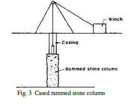
| 1) Bored Rammed System: The bored rammed stone columns are used in cohesive soils. In this technique, a casing pipe is used to remove the cohesive soil protecting the sides of the bore, thus minimizing disturbance to the surrounding soil. The stones are laid into the bore and rammed to a larger diameter as the casing pipe is withdrawn. These columns achieve their strength by the lateral restraint offered by the surrounding soil. It is therefore very essential that the shear strength of the surrounding soil not be reduced by the construction of the stone column. Hence, the stone column technique could be adopted in clays of low sensitivity. These columns also act as drainage paths to accelerate settlements under loading. |
| B. Displacement Method |
| If the soil is laterally displaced while making the hole due to driving of a tube or a casing, it is the displacement type of boring. |
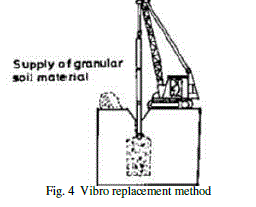
| 1) Vibro Replacement Method: In this method, creation of hole in the ground and compaction of granular fill backfilled in the hole is done mechanically using a mechanical unit called vibrofloat. Stone columns may be constructed using vibrofloat either by Wet process, which is suitable for soft to firm soil with high water table condition where borehole stability is questionable, or by dry process which is suitable for soils of relatively high initial strength with low water table, where the hole can stand of its own upon extraction of the probe, such as unsaturated fills. |
 |
V. INSTALLATION PROCEDURE |
| To form a vibro-replacement point the vibrator with its follower tubes is placed over the selected point by means of a suitable supporting rig (crane). After starting the motor the vibrator is lowered into the ground. It simultaneously releases water from the lower jets which remove the soft soil directly under the vibrofloat nose forming a hole. This operation allows practically an unimpeded penetration of the vibrofloat into the soil under its own weight. No increase in density of the soil is achieved during this operation of the probe penetration. When the vibrofloat has reached the desired depth, the water supply to the lower jet is reduced suitably and the top jets are put on. Wash water from these upper jets returns to the ground surface through the annulus between the outside of the follow on tubes and the crater sides. This upward flow maintains an open channel along the sides of the vibrofloat permitting backfill material shoved from the surface to reach the bottom and it also prevents the probe from sticking. The annular wash water flow is established by raising (surging) the vibrofloat twice or thrice to clean the loose soft soils from the hole. When the water flow continuously returns to the surface, the probe is raised by suitable lift, say 1.5 m and the backfill is poured into the annular space between the poker and the side walls of the hole. The vibrator is then lowered back into the hole between 0.70 to 0.80 m, thereby creating a 0.7m length of stone column. The horizontal vibrations generated by the poker drive the stones laterally into the soil to form a column of an enlarged diameter. Combination of bottom and top water jets may also be used depending upon the soil. Irrespective of the method used to construct the stone columns, the blanket laid over the top of the stone columns should consist of clean medium to coarse sand compacted in layers to a relative density of 75 to 80 percent. Minimum thickness of the compacted sand blanket should be 0.5 m. This blanket should be exposed to atmosphere at its periphery for pore water pressure dissipation. Over the granular blanket, a geotextile mat is laid and then it’s again covered with a granular blanket over which the foundation would rest. This is to uniformly distribute the load coming on the the stone column and there by create a region of uniform loading. |
 |
| A. Top Feed System |
| In the Top Feed System, the poker is completely withdrawn after initial penetration to the design depth. Stone (12-75mm in size) is then tipped into the hole in controlled volumes from the ground surface allowing it to fall under gravity to the bottom side of hole. The column is compacted in layers (the stone is forced downwards and outwards) through continued penetration and withdrawal of the poker. The Top Feed System is suitable if the hole formed by the poker will remain open during construction of the column |
| B. Bottom Feed System |
| The gravel may be fed from a rig-mounted hopper through a permanent delivery tube along the side of the poker, which bends inwards and allows the stone to exit at the poker tip. This Bottom Feed process requires a smaller grade of stone (2-45mm). By remaining in the ground during column construction, the poker cases its own hole and hence is suited to ground with a high water table or running sand conditions. Wet top feed process is called vibro-replacement and dry top/bottom feed process is called vibro displacement |
| VI. DESIGN |
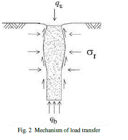
| While stone columns will transmit some load to the soil by shear stresses (along the column-soil interface) and end bearing (at the column base), the predominant load-transfer mechanism (unless the column is very short) is lateral bulging into the surrounding soil. The relevant column stresses are depicted in Fig. 3. The passive resistance of the surrounding soil dictates the column performance under load. Generally the column bulging will be greatest close to the top of the column where the overburden pressures are lowest. |
| A. Design Parameters |
| 1) Stone Column Diameter: Installation of stone columns in soft cohesive soils is basically a self compensating process that is softer the soil, bigger is the diameter of the stone column formed. Due to lateral displacement of stones during vibrations/ramming, the completed diameter of the hole is always greater than the initial diameter of the probe or the casing depending upon the soil type, its undrained shear strength, stone size, characteristics of the vibrating probe/rammer used and the construction method. Diameter usually varies from 800 to 1500 mm |
| 2) Pattern of arrangement: Stone columns should be installed preferably in an equilateral triangular pattern which gives the densest packing although a square pattern may also be used. A typical layout of the patterns are shown in Fig. 7 and Fig. 8 |
| 3) Spacing: The design of stone columns should be site specific and no precise guidelines can be given on the maximum and the minimum column spacing. However, the column spacing may broadly ranges from 2 to 3 depending upon the site conditions, loading pattern, column factors, the installation technique, settlement tolerances, etc. For large projects, it is desirable to carry out field trials to determine the most optimum spacing of stone columns taking into consideration the required bearing capacity of the soil and permissible settlement of the foundation. |
| 4) Replacement ratio: To quantify the amount of soil replaced by the stone, the term replacement ratio, as is used. as = 0.907 (D/S)2 |
| where the constant 0.907 is a function of the pattern used which, in this case, is the commonly employed equilateral triangular pattern. |
| 5) Stress Concentration factor: The stress concentration factor, n, due to externally applied load σ, is defined as the ratio of average stress in the stone column σs ,to the stress σg, in the soil within the unit cell, n=σs/ σg |
| The value of n generally lies between 2.5 and 5 at the ground surface |
| 6) Stress: By assuming a triaxial state of stress in the stone column and both the column and the surrounding soil at failure, the ultimate vertical stress σ1, which the stone column can take, may be determined from the following equation: |
| σ1/ σ3 = (1+sin φs) /(1-sin φs) |
| where |
| σ3 = lateral confining stress mobilized by the surrounding soil to resist the bulging of the stone column; |
| φs = angle of internal friction of the stone column |
| σ1/ σ3 =coefficient of passive earth pressure of the stone column. |
| 7) Settlement: Consolidation settlement of the composite (treated) soil S, is given by: |
| S= mvσgH |
| where |
| mv = Coefficient of volume change |
| σg = Vertical stress in surrounding ground |
| H = Thickness of treated soil |
| 8) Aggregate: Crushed stone or gravel which is chemically inert, devoid of organic matter, hard etc are used for constructing the aggregate column. Well graded stones of 75mm to 2mm may be used. |
 |
VII. FUNCTIONS AND USES |
| Stone column improves the shear strength of the subsoil to increase the bearing capacity. It improves the stiffness of subsoil to decrease settlements. It has the ability to carry very high loads since columns are ductile. It is more economical than piling. Rapid consolidation of subsoil is facilitated in stone column. Immediate increase of shear strength and friction angle of treated soil occurs. There is no waiting period after installation unlike PVD. Embankment construction can begin soon after installation. When installed in a uniform grid pattern it ‘homogenizes’ variable soil properties, thereby reducing the potential for differential settlement. |
VIII. DISADVANTAGES |
| Sensitive clays do not adequately regain shear strength. Due to this, ground improvement by stone column cannot be achieved in clays with sensitivity greater than 4. Stone columns when installed at a distance of less than 3.66m can cause high lateral pressures and displacement of adjacent structures. Severe cracks could be seen in structures close by the stone column site due to the vibrations of 30-50Hz. Stone column installation in extremely cohesive clays and silts is suitable only if preloading facility is available, especially for storage tank construction. |
IX. CONCLUSION |
| The crude form of stone column seen during the construction of Taj Mahal has been improvised greatly and is being made a technically viable option for ground improvement considering it’s cost effectiveness in the recent past. The major conclusions arrived at are as follows: |
| Stone columns improves the bearing capacity and reduces the settlement of weak soil strata |
| Owing to rapid consolidation due to the accelerated dissipation of excess pore water pressure into the drainage path formed by stone columns, construction can be started quickly |
| Thorough subsoil investigation from borelogs supplemented by penetration tests and other insitu test results should be strictly carried out before designing the stone column |
| Stone columns when installed at a distance of 4.87m or more eliminates the damage caused by vibrations |
References |
|