International Journal of Innovative Research in Science, Engineering and Technology
ISSN ONLINE(2319-8753)PRINT(2347-6710)
ISSN ONLINE(2319-8753)PRINT(2347-6710)
| Swagat Pati *1, Sumit Sen Behera *1, Tapan Kumar Pattanaik*1 Department of electrical engineering, Siksha „O? Anusandhan University, Bhubaneswar, Odisha, India |
| Related article at Pubmed, Scholar Google |
Visit for more related articles at International Journal of Innovative Research in Science, Engineering and Technology
To increase the cost effectiveness of generation the amount of power factor should be kept as high as possible. For this to happen the value of reactive power has to be as low as possible. For low power factor loads or low power factor generation systems a back to back bidirectional converter set is employed for the purpose of power factor improvement. Voltage oriented vector control is used for the control of grid-side inverter of a back to back bidirectional converter set for this very purpose. Vector control scheme decouples both the active and reactive power for easy control. This scheme maintains the dc-link voltage at a constant value. This system also finds use in grid interfacing of renewable energy generation systems like Wind energy generation system and solar energy generation system. Vector control scheme for grid-side using P-I controllers is modeled in Matlab and the results are analyzed.
Keywords |
| Grid voltage oriented vector control, DClink voltage control, Grid side inverter, P- I controller. |
INTRODUCTION |
| Now a dayâÃâ¬ÃŸs wind energy has become a smart alternative of clean and renewable energy. Many researchers have been attracted towards doing research in the area due to the fact that wind energy availability is wide spread and abundant on the other hand the sources of conventional energy are depleting day by day. Wind energy conversion systems are of two types i.e. fixed speed wind energy conversion systems and variable speed wind energy conversion systems. |
| Variable speed WECS are in the spotlight in recent days due to their high efficiency and high wind energy capture. Normally three types of machines are used as generators in WECS namely Cage induction motors, doubly fed induction generators and permanent magnet synchronous generators. Out of these three generators DFIGâÃâ¬ÃŸs are the most frequently used generators [4]. This is because of the fact that DFIGâÃâ¬ÃŸs are efficient, robust and flexible for wind energy applications. Again the control of DFIG is done from the rotor side through a pair of bidirectional back to back converters. The rotor side converter is used for improvement of performance(transient and steady state) of the DFIG and the grid side converter is responsible for keeping the DC-link voltage constant at the reference value and improving the rotor side power factor [3,5,7]. Control strategies such as vector control [1, 2, 6, 11, 12] and direct power control [9, 10] can be implemented for the control of grid side converter. Vector control strategy for the grid side converter is a grid voltage oriented decoupled control scheme which results in independent control of active power keeping reactive power at zero [2, 3, 5, 14, 15]. This results in the improvement of the rotor side power factor. Again the active power control of the looped grid side converter maintains the DC-link voltage at a reference value. [3,5,7]. The major benefit of vector control scheme is that it is accurate and has less power quality issues compared to direct power control. Different types of advanced controllers such as sliding mode controller [8] have been implemented for the performance improvement of the grid side converter. |
| In this paper a wind energy conversion system is analyzed which has a doubly fed induction machine as its generator. In this paper the grid side converter control structure is highlighted. The control scheme used in this paper is grid voltage oriented vector control. The vector control scheme employs conventional PI controllers for the control of active and reactive power. This whole scheme is implemented in Matlab/Simulink environment and the results are simulated and analyzed. |
CONTROL SCHEME |
| To maintain the DC-link voltage at a constant value and also to improve rotor side power factor, voltage oriented vector control scheme is implemented on the grid side. The control scheme is shown below. |
| The dc link voltage is |
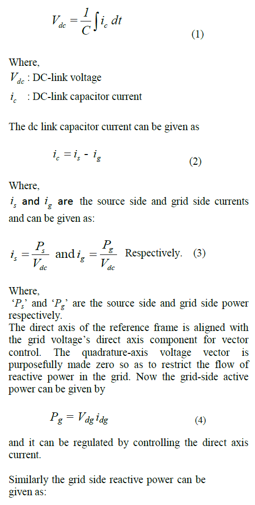 |
| So, Grid side reactive power flow can be controlled by controlling the quadrature axis current „iqgâÃâ¬ÃŸ. There are basically two loops in this system. One for the control of active power and another for control of quadrature axis current to reduce the flow of reactive power. In this method we set the reference quadrature axis current at zero to compare with the real quadrature axis current and then the error signal is sent to the PI controller. This allows unity power factor operation. The direct and quadrature axis voltage equations for the grid side inverter are given as [2, 5] |
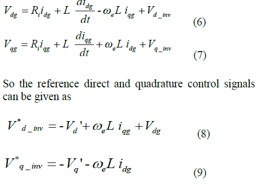 |
INVERTER MODEL |
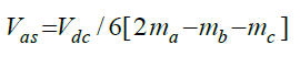
| The inverter that is used is a PWM inverter. The dc-link voltage is inverted and then supplied to the grid through this inverter. The modeling of the inverter goes as follows [6]: |
 |
 |
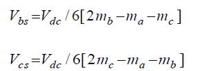 |
| Where, |
| Vas , Vbs and Vcs are the phase voltages and switching states T1 to T6 can either be 1 or 0 depending on their on or off conditions respectively. |
| Vdc : DC link voltage |
| ma: 2T1-1 |
| mb: 2T3-1 |
| mc: 2T5-1 |
PI CONTROLLER DESIGN |
| Controllers are one of the most important components of this arrangement. For a highly efficient system, the controllers need to be accurate and insensitive to change in parameters. Controllers need to be fast and robust to get the desired output. |
| In this arrangement three conventional PI controllers are used. This PI controller can be defined as: |
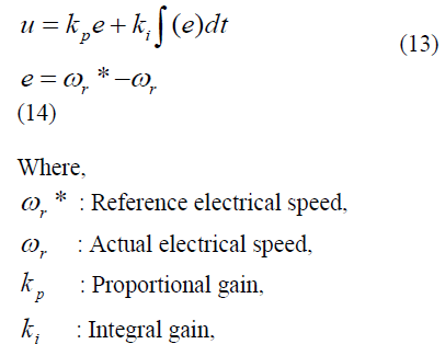 |
| Designing of a PI controller includes the selection of proportional and integral gain values. This process of selection is known as Tuning. In this arrangement the tuning was done by hit and trial method to get the highest efficiency possible. Several other methods like PSO, Zeigler-Nicholas, DE etc can also be adopted to tune the controllers. |
 |
SIMULATION AND RESULTS |
| The sinusoidal PWM scheme which is implemented here is operated at 1 kHz switching frequency. The values of the system parameters used are |
| DC-link capacitor voltage = 250V, |
| DC-link capacitor capacitance =0.002 F, |
| Inductance =0.012 H, |
| Resistance= 0.02 ohm; |
| The entire simulation was done for two categorical values of Active power. They are as follows |
| When power is fed from grid to machine side, |
| When power is fed from machine to grid side (generation). |
| A. When power is fed from grid to machine side: |
| In this as the power flows from grid to machine the power is considered to be positive and the mode of operation of the machine is motoring mode. A step change in active power is applied at 2.5 seconds as shown in fig-3(a), which brings the active power value from 1000 to 2000. In fig-3(a) it can be seen that due to the step change a transient state is developed at 2.5 seconds and the reactive power changes for a short period of time, and a slight overshoot happens. Settling time for both active and reactive power is 0.4 seconds. The maximum overshoot at the transient period, for this set of active power values, for active power is 90W and for reactive power is 168VAR. |
| The dc-link voltage does not change remarkably due to the step change in active power which can be seen in fig- 3(b). |
| Fig3-(c) shows the invariance of power factor and its value at unity except for the transient time which is not clearly visible in this figure. As this system maintains the value of reactive power at zero the grid side power factor is greatly improved. The single phase current of the grid increases at 2.5 seconds which can be observed in fig-3(d). This increase in current is due to the increase in active power. |
 |
 |
| B. When power is fed from machine to grid side (generation): |
| In fig-4(a) it can be observed that when negative active power with a step change from -2000 to -3000 at 2.5 seconds is applied, a transient state arises. In this transient state reactive power takes an undershoot of -200VAR. Settling time for both active and reactive power is 0.4 seconds. The maximum undershoot for active power at the transient period is approximately -113W for the applied set of active power values. |
| Fig-4(b) shows the consistency of dc-link voltage despite of the change in active power. Power factor remains unaffected and steady at unity because of zero reactive power in the system. It is shown in fig-4(c). It is evident from fig-4(d) that when active power is increased at 2.5 seconds the value of the grid current also increases. |
 |
 |
| Fig-3(a) and 4(a) shows the decoupled control of active and reactive power. Even if there is a variation in the active power at the grid side the reactive power is independent of the amount of active power transfer and is kept at zero which is the reference command for reactive power transfer. |
CONCLUSION |
| A vector control scheme for Grid side is designed and simulated in this paper. The results were analyzed, which clearly depicts the decoupled control of active and reactive power. Due to implementation of vector control scheme the Power factor has also improved greatly. Using the vector control scheme a high performance, high speed and efficient system has been designed. |
References |
|