ISSN ONLINE(2319-8753)PRINT(2347-6710)
ISSN ONLINE(2319-8753)PRINT(2347-6710)
Niteen Deshmukh1, Pravin N.Matte2
|
| Related article at Pubmed, Scholar Google |
Visit for more related articles at International Journal of Innovative Research in Science, Engineering and Technology
A wireless measurement and monitoring system for an electric drive system is realized using the ZigBee communication wireless standard for safe and economic data communication in industrial fields where the wired communication is either more expensive or impossible due to physical conditions. It is also possible to protect of the electric drive system against some faults such as over current, over voltage, higher temperature in windings, more load on motor. Therefore, controlling, monitoring, and protection of the system are realized in real time and it uses ZigBee wireless standard for remote data transmission along with Internet connectivity for assessment of the network-collected information. Therefore, the measuring devices and their respective sensors are studied accordingly. Algorithms have been developed allowing evaluation of additional parameters using data from the measurements held.
Keywords |
| ZigBee network, sensors, End-device, Coordinator device, embedded system. |
INTRODUCTION |
| Most of the industrial applications use electric drives which are very popular in because of their simple and safe structures. Hence several controlling methods have been suggested to obtain a better controlling system for them. In past few years, traditional control systems have been replaced with adaptive & intelligent control systems [2]. Toward the start of the 21st century, development in power electronics, electronics, and computer technology has started new progress in automation. Controlling action of electrical drives used in various systems &process control, especially an induction motors, has became very important because of its suitability in system design in industry & it’s so many other advantages such as time, energy & sensitivity [8]. The most important data to drive the induction motor are Frequency, temperature, voltage, current, and speed. The performance of an electric drives is directly affected by whole fundamental qualities. On the other hand, while controlling the machines during the process of production may be dangerous operation in some branches of an industry. In such cases, remote control and monitoring techniques become a considerable solution to eliminate these hazards. Hence, wireless data communication can be used in various industries. |
| Wireless devices using standards like ZigBee are widely used in measurement equipments because of their capabilities to provide easy maintenance, very low energy consumption, data encryption, diverse network topologies, etc. Another advantage of the ZigBee networks is that they allow monitoring parameters of different devices. They are also characterized by much faster installation with respect to the wired systems, which can take many days or may be a weeks to install. ZigBee networks require only the end points to be installed such that it saves users much time. |
| Nowadays, such wireless systems are often applied for monitoring and control in many areas such as manufacturing processes, robotics, building automation, etc. Some implementations of wireless control in industry for robots and manipulation systems are described in [9]. An industrial real-time measurement and monitoring system based on ZigBee standard is presented in [10]. An increased interest in this standard for building automation has been registered recently [9]. Remote wireless systems are also suitable for monitoring of various environmental parameters such as: air pollution, humidity, temperature, pressure, etc. [5] |
| Especially, for monitoring of electric drive systems, measurement of various parameters such as voltage, current, torque, distance, speed, position, temperature, energy consumption, battery charge and vibrations may be required. Some applications of appropriate devices for wireless data transfer are described in [3, 4]. |
| The main aim of this paper is to presents the design of a modular wireless sensing system for monitoring of electric drives suitable for industrial and home applications. It uses ZigBee standard for remote data transmission combined with Internet connectivity for assessment of the Global network-collected information. The system developed includes a ZigBee network of intelligent measurement modules combined with a coordinator device with GSM or Ethernet modem. The ZigBee standard provides high reliability and immunity against any narrow-band interferences. A coordinator device realizes data acquisition and the network management. It also expands the low-range ZigBee network to a widespread range. The system measurement devices can be installed at almost any place because of their compact sizes. In addition, the monitoring system flexibility allows its utilization in a variety of practical applications. |
II. LITERATURE SURVEY |
| WI- Fi, 3G, Bluetooth, ZigBee are the example of Wireless communication which is capable of high data transmission rate. These devices use system resources a largely and are proportional to transmission speed. The Institute of Electrical and Electronics Engineers (IEEE) developed 802.15.4 standards and helped the production of ZigBee protocol and devices that support this protocol. As a result, ZigBee supported devices have intelligent network topologies, low-cost, and are have energy saving features. So that they have their own place in daily life and industrial companies in number of ways [6]. A various number of devices and machines can be controlled along with data transmission and reception at the same time with ZigBee wireless technology. So, system running can be achieved without any trouble [7]. In the literature, many numbers of methods has been used for monitoring, running and detecting electrical & mechanical defects in electric drives. |
| Traditional protection practices for detecting electric drive defects uses various types of protection relays such as temperature relays, over current relays, electromagnetic switches, low and high current protection relays, time relays and contactors. If the traditional protection methods are compared with the computer-based methods, traditional methods considerably reduce the sensitivity and efficiency of the system because many of the mechanical parts including in the system increase the time for detecting defects. Another disadvantage of the traditional protection methods is their cost. We know that traditional methods increase the cost of systems while a digital system decreases it. There are many publications on detection of the mechanical defects of induction motors in the literature [4]. In some studies, electric drive parameters have been used to display the electrical and mechanical performance of the drives through a PC. In [11], a real time monitoring system has been developed against the failure of electric drive. All measurements related to the electric drive were done. However, it was realized that the cost is increased due to use of sensors to collect the current and the voltage information from the network and transfer them to the computer by an analogue/digital converter card. |
A. ZigBee characteristics |
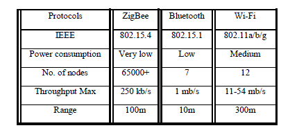
| ZigBee is a short-distance, simple-structured, low power, and low-transmission rate wireless communications technology. It has a transmission range of 100 m and uses the free 900 MHz and 2.4 GHz transmission frequencies. ZigBee has a transmission rate of 20 Kbps to 250 kbps; its network structure has Master/ Slave attributes and can provide the function of two-way communication. Currently, ZM03 uses the 2.405–2.480 GHz frequencies; in addition, due to the low transmission rate and small amount of data transmitted, the sending and receiving time is kept low. In non-work mode, ZigBee is placed in sleep mode. In the conversion time between work and sleep modes, only 15 ms are needed for normal sleep activation time and only 30 ms are needed in the equipment search time, making ZigBee fairly power-saving. The MAC level of ZigBee utilizes a talk-when-ready collision prevention mechanism: data is transmitted immediately when there is need, and each transmitted data packet is confirmed to be received by receiver and is responded to with a confirmation message; if a confirmation message is not received in response, then a collision has occurred and the data packet is transmitted again. This method greatly increases the reliability of the system’s data transmission. In addition, a ZigBee network can include a maximum of 255 nodes, making it highly expandable [10]. |
B. Comparison of ZigBee with other wireless communications services |
| In comparing ZigBee with other wireless communications technologies in terms of the wireless communications technology faces of area networks and personal networks, 802.11- series technologies (Wi-Fi) are centered on wireless local area networks (WLAN) for use in data transmission. On the other hand, Bluetooth, UWB, and ZigBee are wireless personal area networks (WPAN) technologies. The Bluetooth standard has a transmission rate of hundreds of Kbps and is thus appropriate for data transmission; it also has the QoS mechanism for voice applications. The UWB (ultra wideband) has high-speed and QoS, making it appropriate for multimedia applications. Characteristics of the ZigBee standard include low power and low-cost, so it fits the control and sensing needs in industry, family, and medicine; ZigBee does not have high requirements for data transmission rate and QoS. In addition, in comparing the currently- popular Bluetooth technology and ZigBee, ZigBee consumes far less power than Bluetooth; due to its low power consumption, ZigBee has a lower transmission rate compared to Bluetooth. In terms of the expansion flexibility of network node quantity, ZigBee has very strong capability in range expansion due to its support of mesh topology. Fields of application for ZigBee include family automation, family security, overall medical care in hospitals, and industrial automation. ZigBee can be used in conjunction with products such as home appliances, consumer electronics, PC peripherals, and sensors, providing functions such as home appliance sensing, wireless PC peripheral control, and home appliance remote control [10] |
 |
III. DESIGN OF PROPOSED MEASUREMENT SYSTEM |
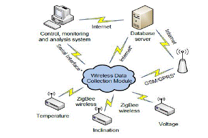
| The general structure of the developed wireless sensor system is presented in Fig. 1. It consists of one wireless data collection module (ZigBee coordinator device), end-devices (measuring devices), database server which is accessed via Internet and a module for system control and data visualization. |
| The coordinator device reads data measured from remote end-devices and retransmits them to the database server. The wireless connection between end-devices and the coordinator device is facilitated through their ZigBee modules. The database server and the coordinator device can be connected in three ways: through a personal computer, an Internet modem or a GSM/GPRS modem. |
| This measurement system includes three communication modules (GSM/GPRS, ZigBee and Ethernet modem) and several end-devices for monitoring temperature, current and voltage. Such a modular concept allows us to combine the different types of measuring devices along with various communication capabilities, environmental conditions and requirements. Each one of the measuring devices can be used independently or can be used as a part of the complex system. |
A. Coordinator device |
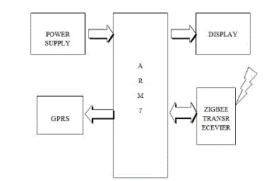
| The coordinator device can be used as standalone measurement equipment with diverse communication capabilities. To facilitate the wireless network coordinating function, it may be equipped with a GSM/GPRS, ZigBee module, or may be Ethernet modem for expanding the system over the Internet. The coordinator device can also be used as a data logger. |
 |
| A. Microcontroller: Its main function is to acquire sensor data and manage the ZigBee wireless network. It implements radio channel configuration, network ID, remote sensor data acquisition, end-device association, and end-device ID configuration, etc. The microcontroller also performs controlling and configuration of different communication modules such as ZigBee, GSM/GPRS and Ethernet. |
| B. ZigBee: The ZigBee module is used to provide wireless connection between the coordinator device and the measuring end-devices. It is controlled by standard AT commands over a serial communication interface. ZigBee has very low power consumption and is quite suitable for battery powered systems. |
| C. GSM/GPRS: This module is used as a gateway between the ZigBee module and the database server. It is also controlled via standard AT commands over a serial communication interface. It is applied to retransmit the acquired sensor data over the mobile cellular network to the Internet connected database using the GPRS data channel. It provides mobility of the designed system. |
| D. Ethernet: This component provides a direct access to the database server. The developed measuring system utilizes SNMP protocol on the application layer. The measured data is transmitted from coordinator device to the Ethernet module via serial line. After that it can be saved and read in the database through the SET and GET SNMP commands. A specially designed program script is used for data acquisition from the coordinator device via Ethernet interface. |
| E. Sensors and input measuring channels: The coordinator device incorporates two temperature channels for monitoring the temperature of a monitoring device and the ambient temperature. Digital temperature sensors, SMT-160 used by the system which provides accuracy of about +/- 0.7 °C and supply current of about 200 micro-Ampere. |
| The coordinator device has one current input that can be used for connecting current transducer such as LA 125-P. This sensor uses Hall closed-loop technology and has an accuracy of about +/- 1 A in the entire measuring range of -125 to +125 A. The current input can be used as an information input for connecting to a standard industrial device with 0/4 ÷ 20 mA analog output. |
| The second analog input is used to measure voltage. It is configured to measure voltages in the range of 0 to 300 VDC, depending on the input divider. Together with the current input it can also be used to measure charging or discharging cycles of various accumulator batteries. In this case, the coordinator device should be connected to a standard industrial device with analogue voltage output in the range 0 ÷ 10 VDC. |
| a) Real time clock and EEPROM: Real time clock (RTC) implements the time synchronization. When this device is used as a data logger, it provides the measurement interval between two adjacent data samples. The RTC has its own internal RAM along with independent backup power supply that allowing it to store device parameters such as logging time interval, calibration constants, etc. |
| b) EEPROM: It can be used to store the measured data. The user can select which data channels to be saved and the time interval between two samples of the measured data. |
| c) Power supply: In order to implement the system along with its full functionality, the coordinator device is powered by +/- 12 VDC. Such a bipolar voltage is required by the current sensor LA 125-P. In some case if this input is not implemented, the device can utilize only +12 V power supply. |
 |
B) End-devices |
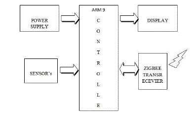
| The block diagram showing one of the end-measuring devices is shown in Fig. 3. Its main function is to measure temperature from resistive temperature sensors such as thermistors or platinum sensors. Differentiating the digital temperature sensors of the coordinator device, the end-device resistive sensors achieve faster response time (thermistors) and greater accuracy (platinum). Depending on the system’s measuring requirements, we can use either the much more accurate platinum sensors or low cost thermistors for temperature measurement. |
 |
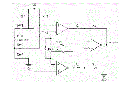
| The figure 4 has shown an input temperature channel. For reducing errors caused by the connecting wires resistance, the platinum sensors are connected using 3-wire connections in bridge circuit [10]. On the figure present below, each wire is represented as a resulting resistance Rw1, Rw2 and Rw3. In the figure, it is given that the resistance Rw1 and |
| Rw2 are equal, as well as the currents flowing through them, the respective voltage drops compensate each other. The sensing analog channel consists of an instrumentation amplifier and a 16 bit A\D converter. The input channel is used by thermistors and depending upon0 the sensor only the bridge values must be recalculated. The microcontroller software must also be changed. |
 |
| In order to store energy, all battery powered devices work based on the following algorithm discuss below: |
| Data measurements are carried out in strict time intervals; hourly collected data are stored into the EEPROM (in case of battery or other failure only the last hour data will be lost); data are acquired from the end-devices once a day or in longer periods of time to preserve the battery energy. The ZigBee device module has low-power consumption. However, transmitting data over the radio channels decrease battery life. |
IV. REVIEW OF RESULT PERMOMED ON AC ELECTRIC DRIVE SYSTEM |
| Here some of the result obtained from reference paper [1] and system is developed for the A.C. electric drive. As the system developed various parameters of electric drive so that systems can be measured and many others parameter can be calculated based on them. Some of the graphical presentations of sensors acquired data and algorithms are given for evaluation of additionally monitored parameters. |
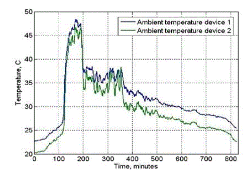
| Ambient temperature is measured simultaneously by the coordinator device and the end-device (Fig. 5). Both have different types of temperature sensors and are placed at a distance from each other in a room with operating electrical motors. The time diagrams illustrate a constant offset of about 2o C between the two measured temperatures. This is because of their different location and the lower accuracy of the digital sensor (SMT160) in comparison with the resistive one (platinum). |
| The illustrated data shown in Fig. 6 have been collected in a period of 14 hours with an interval of one minute. The sensing network that is used in the system started collecting data at night and stopped after 14 hours. According to the graphic shown below, the daylight cycle began around 100th minute. The increase in temperature indicates the sunrise. From the presented values it can be concluded that during the day the working environment temperature reaches up to 47oC. |
 |
| The main advantage of this wireless system is that we get accurate temperature measuring device can be used or a low cost one depending on the particular user requirements. |
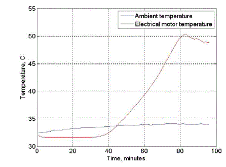
| Fig. 6 that is shown below represents experimentally obtained results from remote temperature monitoring of an induction motor in an AC electric drive system with frequency control. In this driving system, a 3-phase voltage source inverter along with tracking pulse width modulation is used. In the interval shown in the figure, both the motor and ambient temperatures are tracked. |
 |
V. CONCLUSIONS |
| Detailed experimental studies confirm the good performance of this efficient embedded system. The research carried out as well as the results obtained can be used in design and set up of such types of remote monitoring systems for electric drives in industry and home applications An embedded system for remote monitoring of electric drives has been developed and described. The structure presented is flexible due to the utilized ZigBee to allow measurement of maximum parameters such as current, speed, energy consumption, voltage, temperature, vibrations, and many more. The Appropriate algorithm has been developed for analysis & evaluation of additional characteristics using data taken from measurement done by the system. |
| The system that we are developing can not only used by industrial applications but also for educational purposes; which means, the whole system may be useful to colleges or universities such that they can provide vocational, technical, and industrial education. Instructors can use the above system as a supporting teaching material, and it can be accepted in experimental researches successfully. |
References |
|