International Journal of Innovative Research in Science, Engineering and Technology
ISSN ONLINE(2319-8753)PRINT(2347-6710)
ISSN ONLINE(2319-8753)PRINT(2347-6710)
| Kuldeep B1, Arun L.R2, Mohammed Faheem3 P.G. Scholar, Department of Mechanical Engineering, The Oxford college of Engineering , Karnataka, India1,3 Associate Professor, Department of Mechanical Engineering, The Oxford college of Engineering, Karnataka, India2 |
| Related article at Pubmed, Scholar Google |
Visit for more related articles at International Journal of Innovative Research in Science, Engineering and Technology
Connecting rod is the intermediate link between the piston and the crank. And is responsible to transmit the push and pull from the piston pin to crank pin, thus converting the reciprocating motion of the piston to rotary motion of the crank. Generally connecting rods are manufactured using carbon steel and in recent days aluminium alloys are finding its application in connecting rod. In this work connecting rod is replaced by aluminium based composite material reinforced with silicon carbide and fly ash. And it also describes the modelling and analysis of connecting rod. FEA analysis was carried out by considering two materials. The parameters like von misses stress, von misses strain and displacement were obtained from ANSYS software. Compared to the former material the new material found to have less weight and better stiffness. It resulted in reduction of 43.48% of weight, with 75% reduction in displacement.
Keywords |
| connecting rod, ANSYS, composite, silicon carbide, fly ash, analysis |
INTRODUCTION |
| Connecting rod is the intermediate link between the piston and the crank. And is responsible to transmit the push and pull from the piston pin to crank pin, thus converting the reciprocating motion of the piston to rotary motion of the crank. Connecting rod, automotives should be lighter and lighter, should consume less fuel and at the same time they should provide comfort and safety to passengers, that unfortunately leads to increase in weight of the vehicle. This tendency in vehicle construction led the invention and implementation of quite new materials which are light and meet design requirements. Lighter connecting rods help to decrease lead caused by forces of inertia in engine as it does not require big balancing weight on crankshaft. Application of metal matrix composite enables safety increase and advances that leads to effective use of fuel and to obtain high engine power. Honda Company had already started the manufacturing of aluminium connecting rods reinforced with steel continuous fibers. By carrying out these modifications to engine elements will result in effective reduction of weight, increase of durability of particular part, will lead to decrease of overall engine weight, improvement in its traction parameters, economy and ecological conditions such as reduction in fuel consumption and emission of harmful substances into atmosphere K. Sudershan kumar [1] et al, described modeling and analysis of Connecting rod. In his project carbon steel connecting rod is replaced by aluminium boron carbide connecting rod. Aluminium boron carbide is found to have working factory of safety is nearer to theoretical factory of safety, to increase the stiffness by 48.55% and to reduce stress by 10.35%. Vivek. C. Pathade [2] et al, he dealt with the stress analysis of connecting rod by finite element method using pro-e wild fire 4.0 and ansys work bench 11.0 software. And concluded that the stress induced in the small end of the connecting rod are greater than the stresses induced at the bigger end, therefore the chances of failure of the connecting rod may be at the fillet section of both end. Pushpendra kumar Sharma [3] et al, performed the static FEA of the connecting rod using the software and said optimization was performed to reduce weight. Weight can be reduced by changing the material of the current forged steel connecting rod to crackable forged steel (C70). And the software gives a view of stress distribution in the whole connecting rod which gives the information that which parts are to be hardened or given attention during manufacturing stage. Ram bansal [4] et al, in his paper a dynamic simulation was conducted on a connecting rod made of aluminium alloy using FEA. In this analysis of connecting rod were performed under dynamic load for stress analysis and optimization. Dynamic load analysis was performed to determine the in service loading of the connecting rod and FEA was conducted to find the stress at critical locations. |
II. THEORETICAL CALCULATION OF CONNECTING ROD |
| 1. Pressure calculation: |
| Consider a 150cc engine |
| Engine type air cooled 4-stroke |
| Bore × Stroke (mm) = 57×58.6 |
| Displacement = 149.5CC |
| Maximum Power = 13.8bhp at 8500rpm |
| Maximum Torque = 13.4Nm at 6000rpm |
| Compression Ratio = 9.35/1 |
| ïÃâ÷ Density of petrol at 288.855 K - 737.22*10-9 kg/mm3 |
| ïÃâ÷ Molecular weight M - 114.228 g/mole |
| ïÃâ÷ Ideal gas constant R – 8.3143 J/mol.k |
| From gas equation, |
| PV=m.Rspecific.T |
| Where, |
| P = Pressure |
| V = Volume |
| m = Mass |
| Rspecific = Specific gas constant |
| T = Temperature |
| But, |
| mass = density * volume |
| m =737.22E-9*150E3 |
| m = 0.11 kg |
| Rspecific = R/M |
| Rspecific = 8.3143/0.114228 |
| Rspecific = 72.76 |
| P = m.Rspecific.T/V |
| P = 0.11*72.786*288.85/150E3 |
| P = 15.4177 MPa |
| P ~ 16 MPA. |
| 2. Design calculation of connecting rod: |
| In general |
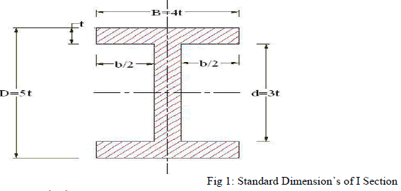 |
| From standards, |
| ïÃâ÷ Thickness of flange and web of the section = t |
| ïÃâ÷ Width of the section B = 4t |
| ïÃâ÷ Height of the section H = 5t |
| ïÃâ÷ Area of the section A = 11t2 |
| ïÃâ÷ Moment of inertia about x axis Ixx= 34.91t4 |
| ïÃâ÷ Moment of inertia about y axis Iyy= 10.91t4 |
| ïÃâ÷ Therefore Ixx/Iyy = 3.2 |
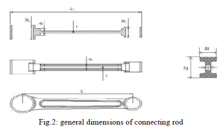
| So, in the case of this section (assumed section) proportions shown above will be satisfactory. Length of the connecting rod (L) = 2 times the stroke |
| L = 117.2 mm |
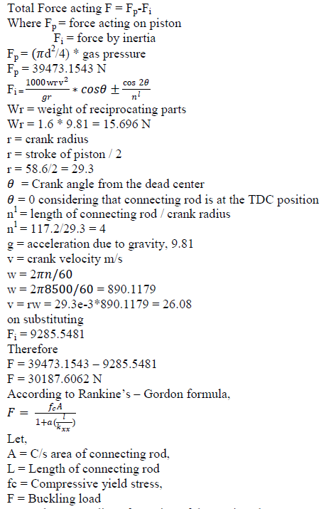 |
| Ixx and Iyy = Radius of gyration of the section about x – x and y – y axis respectively and Kxx and Kyy = Radius of gyration of the section about x – x and y – y axis respectively. |
| 1. For aluminium 360 |
| On substituting to rankine’s formula |
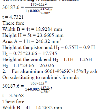 |
| Height H = 5t = 17.829 mm |
| Area A = 11t = 139.8642 mm2 |
| Height at the piston end H1 = 0.75H – 0.9 H |
| H1 = 0.75*23.66 = 13.37 |
| Height at the crank end H2 = 1.1H – 1.25H |
| H2 = 1.1*23.66 = 19.6119 |
 |
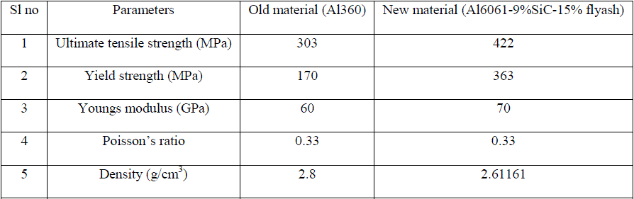 |
| TABLE 1 MATERIAL PRORTIES USED FOR ANALYSIS |
III. FEA OF CONNECTING ROD |
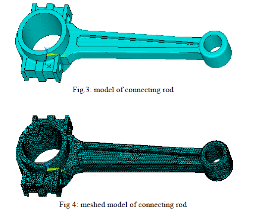 |
| Type of Element : solid 187 |
| Number of Nodes : 117439 |
| Number of Elements : 69613 |
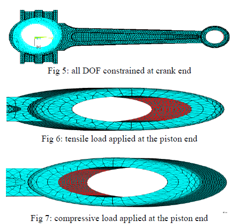
| ïÃâ÷ Loads and constraints: |
 |
IV. RESULTS AND DISCUSSION |
| ïÃâ÷ ANALYSIS |
| For the finite element analysis 16 Mpa of pressure is used. The analysis is carried out using ANSYS software. The pressure is applied at the small end of connecting rod keeping big end fixed. The maximum and minimum vonmisses stress, strain and displacement are noted from the ANSYS. |
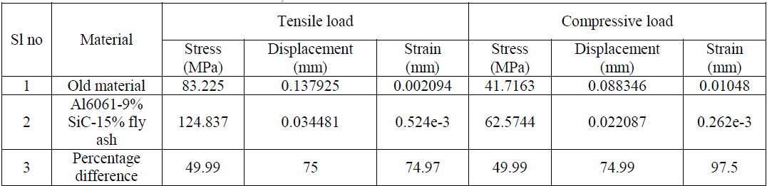 |
| Table 2 COMPARISON OF STRESS, STRAIN AND DISPLACEMENT FOR DIFFERENT MATERIALS |
| 1. VON-MISES STRESS PLOTS: |
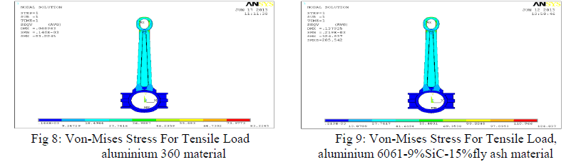 |
| From the fig 8 the maximum stress occurs at the piston end of the connecting rod is 83.2245 Mpa and minimum stress occurs at the crank end of the connecting rod is 0.146e-03 Mpa. From the fig 9 the maximum stress occurs at the piston end of the connecting rod is 124.837 Mpa and minimum stress occurs at the crank end of the connecting rod is 0.219e- 03 Mpa. |
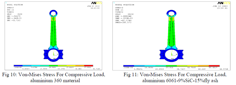 |
| From the fig 10 the maximum stress occurs at the piston end of the connecting rod is 41.7163 Mpa and minimum stress occurs at the crank end of the connecting rod is 0.146e-3 Mpa. From the fig 11 the maximum stress occurs at the piston end of the connecting rod is 62.574 Mpa and minimum stress occurs at the crank end of the connecting rod is 0.220e-3 Mpa. |
| 2. Displacement plots |
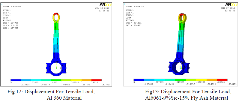 |
| From the fig 12 the maximum displacement occurs in the connecting rod is 0.137925 mm. From the fig 13 the maximum displacement occurs in the connecting rod is 0. 034481 mm. |
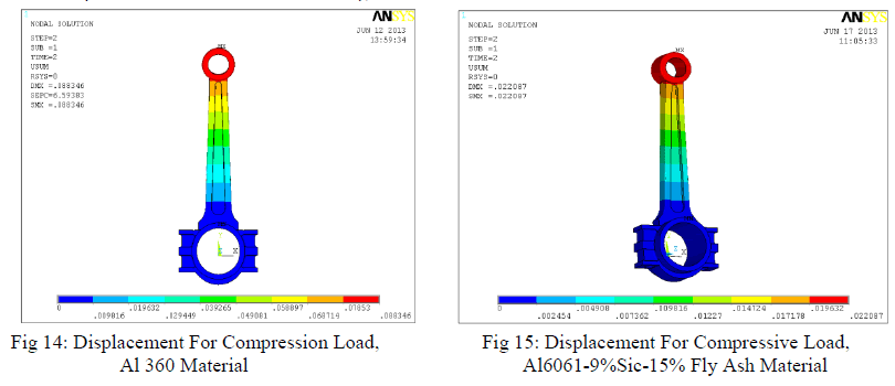 |
| From the fig 14 the maximum displacement occurs in the connecting rod is 0. 088346 mm. From the fig 15 the maximum displacement occurs in the connecting rod is 0. 022087 mm. |
| 3. Von-mises Strain plots |
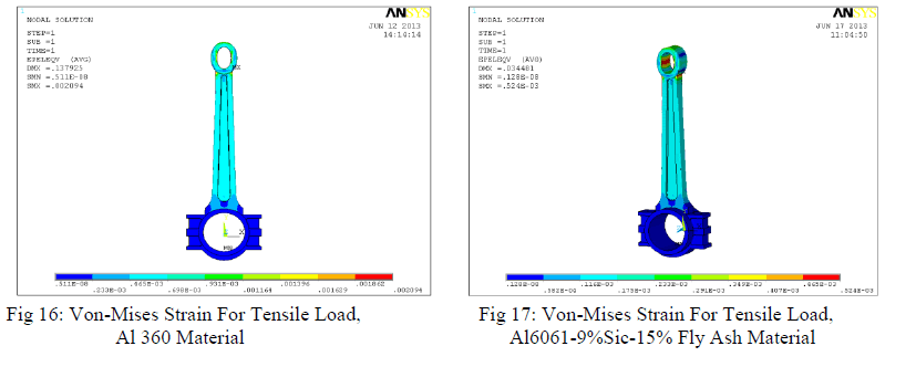 |
| From the fig 16 the maximum Von-mises strain occurs at the piston end of the connecting rod is 0.002094mm and minimum Von-mises strain occurs at the crank end of the connecting rod is 0.511e-08mm. From the fig 17 the maximum Von-mises strain occurs at the piston end of the connecting rod is 0.524e-03 mm and minimum Von-mises strain occurs at the crank end of the connecting rod is 0.128e-08mm. |
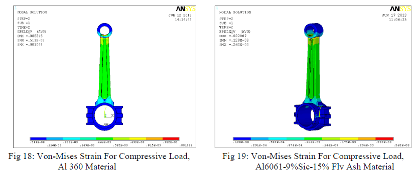 |
| From the fig 18 the maximum Von-mises strain occurs at the piston end of the connecting rod is 0.001048mm and minimum Von-mises strain occurs at the crank end of the connecting rod is 0.511e-08mm. From the fig 19 the maximum Von-mises strain occurs at the piston end of the connecting rod is 0.262e-03 mm and minimum Von-mises strain occurs at the crank end of the connecting rod is 0.128e-08mm. |
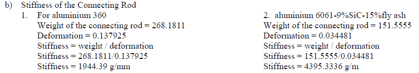
| 4. VOLUME, WEIGHT AND STIFFNESS OF THE CONNECTING ROD |
| a) Weight of the Connecting Rod. |
| ïÃâ÷ For aluminium 360: |
| The volume of the connecting rod used is 100829.348 mm3. Therefore the mass of the connecting rod for respective materials are: |
| Weight = volume * density |
| Weight = 100829.348 * 2.63 e-3 |
| Weight = 268.1811 grams |
| ïÃâ÷ For aluminium 6061-9%SiC-15%fly ash |
| The volume of the connecting rod used is 57472.72836 mm3. Therefore the mass of the connecting rod for respective materials are: |
| Weight = volume * density |
| Weight = 57472.72836 * 2.637009e-3 |
| Weight = 151.5555 grams |
| Therefore there is net difference of 116.6256 grams in the new connecting rod for the same volume, i.e., is 43.48 % reduction in weight. |
 |
V. CONCLUSION |
| ïÃâ÷ WEIGHT CAN BE REDUCED BY CHANGING THE MATERIAL OF THE CURRENT AL360 CONNECTING ROD TO HYBRID ALFASIC COMPOSITES. |
| ïÃâ÷ THE OPTIMISED CONNECTING ROD IS 43.48% LIGHTER THAN THE CURRENT CONNECTING ROD. |
| ïÃâ÷ THE NEW OPTIMISED CONNECTING ROD IS COMPARATIVELY MUCH STIFFER THAN THE FORMER. |
References |
|