ISSN ONLINE(2319-8753)PRINT(2347-6710)
ISSN ONLINE(2319-8753)PRINT(2347-6710)
Shankara Murthy.H.M1, Madhukeshwara.N2, S.Kumarappa3
|
| Related article at Pubmed, Scholar Google |
Visit for more related articles at International Journal of Innovative Research in Science, Engineering and Technology
In this work two dimensional CFD analysis have been carried out to predict the aerodynamic forces on the surface of the NACA 64618 airfoil at High Reynolds number of 9 million. The study focus on understanding the accuracy of the results obtained with different near wall modelling techniques. Computing the near wall flow region by two distinct approaches Viz. Direct resolution of shear stresses (Mentors SST Model) and use of wall function (K-ε Model) is assessed.CFD analysis results are compared with the wind tunnel test data available in the literatures. The reasons for deviation between CFD analysis results and wind tunnel test data are investigated and accurate procedure for modeling the near wall flow region is concluded.
Keywords |
| Computational Fluid Dynamics (CFD), Airfoil, Aerodynamic Coefficients, Lift, Drag, Turbulence Models, Stalling, Boundary layer, Turbulence model, Angle of attack. |
INTRODUCTION |
| The rapid evolution of computational fluid dynamics (CFD) has been driven by the need for faster and more accurate methods for the calculations of flow fields around configurations of technical interest. In the past decade, CFD was the method of choice in the design of many aerospace, automotive and industrial components and processes in which fluid or gas flows play a major role. In the fluid dynamics, there are many commercial CFD packages available for modeling flow in or around objects. The computer simulations show features and details that are difficult, expensive or impossible to measure or visualize experimentally. Viscous fluid flow analysis using Computational Fluid Dynamics (CFD) methods focuses mainly on accurate prediction of near wall boundary layer region. In the case of external aerodynamics flow, CFD analysis results like li ft and drag forces depends greatly on the proper resolution of near wall physics, especially in the stalling region. Assessing the lift and drag forces on the sectional airfoil profile is a significant stage in Aerodynamic design of systems like Aircraft wings, Turbo machinery cascades, wind turbine rotor blade etc. David Hartwanger et.al [06] conducted CFD analysis for NREL S809 airfoil section of the wind turbine blade using the 2d panel code X-Foil and ANSYS CFX 2D code. The work concluded that using a high-resolution structured mesh; with advanced turbulence and transition models provide an excellent match with experimental data in the attached flow regime. However, the CFD and XFOIL panel code over-predict peak lift and tend to underestimate stalled flow. Franck bertagnolio et.al [07] discusses the experimental and 2D CFD simulation results for the NACA six digit wing section families. The work concluded that results obtained with Ellipsys 2D research code provides a good match with experimental data both in the attached and stalled flow regimes. Ellipsys 2D CFD code uses the shear stress transition turbulence model to predict the turbulence effects accurately as well as the flow transition from laminar to turbulent regime. This option is not available in the commercial CFD solvers. H.Gao et.al [08] conducted experimental and CFD simulations for corrugated dragonfly airfoil at low Reynolds number (Re=55000 to 68000).2D and 3D CFD simulations are conducted using MUSIC Navier-Stokes solver. The work concluded that 2D and 3D CFD results differ significantly at relatively high angle of attacks and 3D CFD results agree much better with the experimental data. It is concluded that vortex dominated flow at higher angle of attacks is strongly threedimensional. Literatures cited in this field indicates that the Turbulence models employed in most of the commercial CFD software’s treat the boundary layer around the airfoil as fully turbulent and hence the drag forces are over predicted and the results obtained with these turbulence models underestimates the stalled region. Needs to be properly implemented in CFD analysis in order to have a reliable prediction in stalling, pre stall and post stall region. |
II.MATHEMATICAL MODELS |
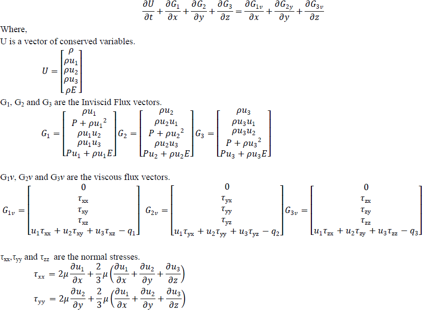
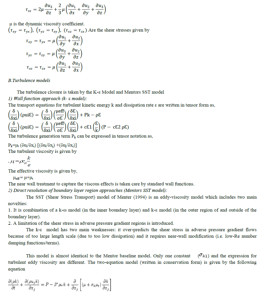
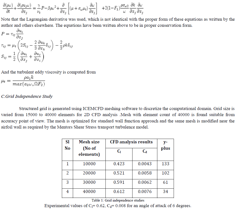
| The commercial FLUENT software package, FLUENT 6.3.26, was used for solving the set of governing equations. The numerical method employed is based on the finite volume approach. Fluent provides flexibility in choosing discretization schemes for each governing equation. A.Governing Equations The Governing Navier-Stokes equations for the flow physics considered in this work are written in vector form as |
 |
 |
 |
| D.Boundary conditions There are three faces bounding the calculation domain namely: the inlet boundary, the wall boundary and the outlet boundary. No-Slip boundary conditions are applied along the solid walls and wall functions were used as described earlier.The inlet boundary conditions involve total pressure and velocity direction cosines for varying angle of attack, turbulence intensity and turbulent viscosity ratio. The velocity components are calculated for each angle of attack as follows. The x-component velocity direction cosine is calculated by x=ucosα and the y component velocity direction cosine is calculated by y=usinα, where α is the angle of attack in degrees. The inlet velocity (U) is 132 m/sec for a free stream Reynolds number of 9 million and air at STP (Temperature=150c, Pressure=1.01325 bar) as the fluid medium. Ambient |
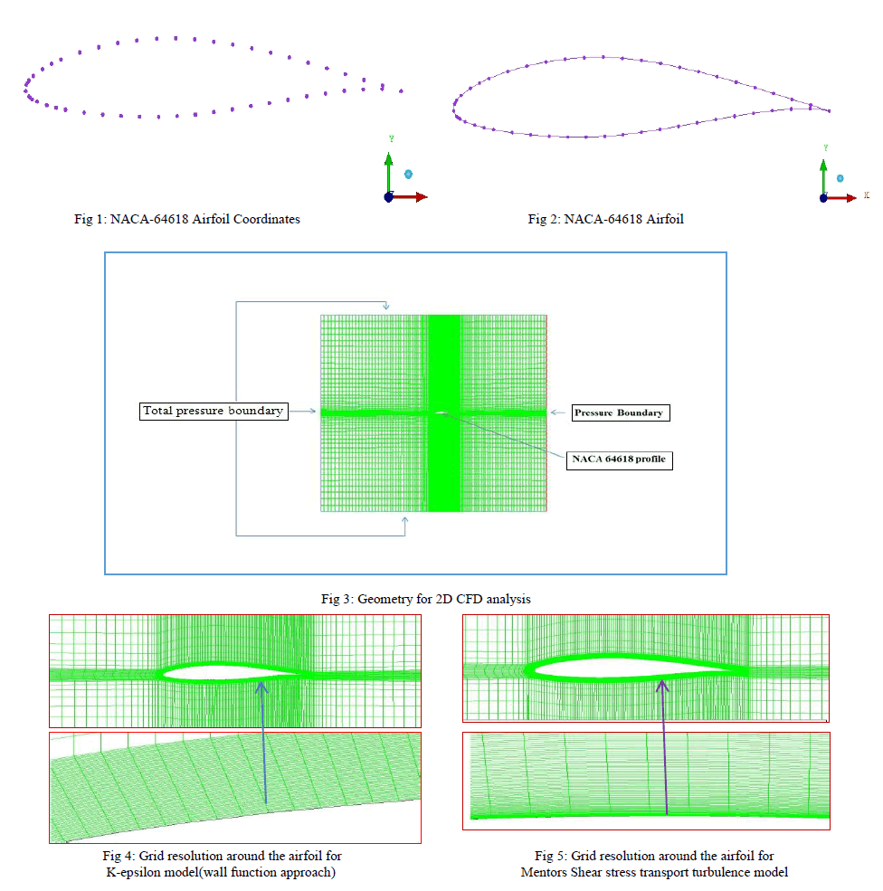
| atmospheric condition is imposed at outlet. Turbulent intensity and viscosity ratio conditions are set to a value of 5 as per the industry practices. E.Geometrical Modeling and Grid Generation |
 |
III.RESULTS AND DISCUSSIONS |
 |
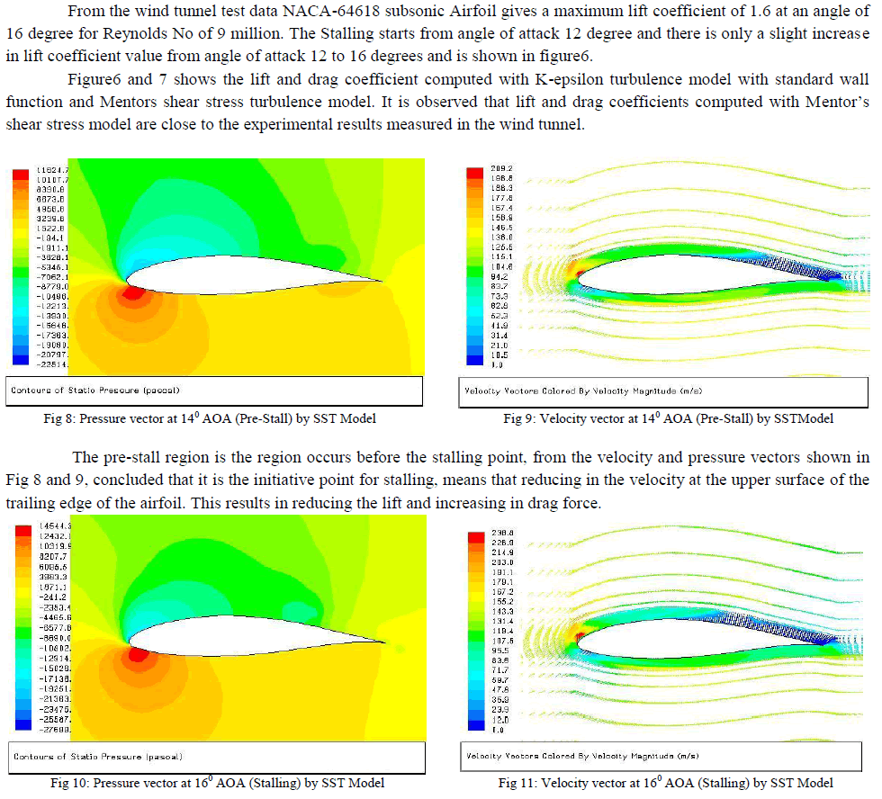 |
| Stalling point is the point at which the reduction in the lift force is maximum and increasing in Drag, and also the velocity at the upper surface of the trailing edge is almost equal to zero that we see from figures 10 and 11. It is observed that the flow separation region is well captured by the Mentors shear stress model and hence the Mentors shear stress model is correctly predicting the lift coefficient in the stalled region. |
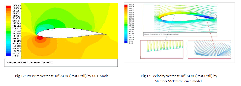 |
| From figure 13 it is observed that the flow separation region is well captured by the Mentors shear stress model and hence the Mentors shear stress model is correctly predicting the lift coefficient in the stalled region. |
IV. CONCLUSION |
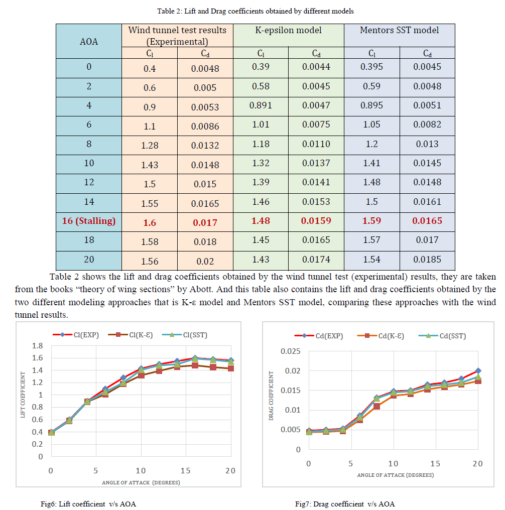
| From the above discussions the lift and drag coefficients taken from the experimental wind tunnel test results are 1.6 and 0.017 respectively at an angle of attack 160 (Stalling Region).similarly 1.48 and 0.0159 are Lift and Drag coefficients obtained by the K-ε Model, 1.59 and 0.0165 are Lift and Drag Coefficients obtained by the Mentors SST turbulence model. It is observed that lift and drag coefficients computed with Mentor’s shear stress model are close to the experimental results measured at the wind tunnel. And the flow separation region is well captured by the Mentors shear stress model and hence the Mentors shear stress model is correctly predicting the lift coefficient in the stalled region. Hence it is concluded that Mentors shear stress transport Turbulence model employing the direct resolution of boundary layer region by a fine mesh gives the accurate CFD analysis results in the pre stall as well as post stall region. |
References |
|