ISSN ONLINE(2319-8753)PRINT(2347-6710)
ISSN ONLINE(2319-8753)PRINT(2347-6710)
Vivekananthan Karthikeyan1, Ssheshan Pugazhendhi2, Sai Krishnan Subramanium3, Antony Aroul Raj V4
|
| Related article at Pubmed, Scholar Google |
Visit for more related articles at International Journal of Innovative Research in Science, Engineering and Technology
Jet impingement systems provide an effective means for the enhancement of convective processes due to the high heat and mass transfer rates that can be achieved. The range of industrial applications that impinging jets are being used in is wide. In the annealing and tempering of materials, impinging jet systems are finding use in the cooling of hot metal, plastic, or glass sheets as well as in the drying of paper and fabric. Compact heat exchangers, with applications in the aeronautical or the automotive sector, often use multiple impinging jets in dense arrangements. In gas turbine applications, jet impingement has been routinely used for a long time. Because of increased thermal efficiency at high turbine inlet temperatures, many gas turbine components, such as rotor disks, turbine vanes and blades, or combustion chamber walls, are operated at temperatures well above highest allowable material limits. In order to assure durability and long operating intervals, effective cooling concepts are required for these highly loaded components.The current work involves studying of effect of spanwise jet-to-jet spacing on local heat transfer distribution due to an in-line rectangular array of confined multiple circular air jets impinging on a surface parallel to the jet plate computationally. Shear Stress Transport (SST) k-ω turbulence model is used. The flow, after impingement, is constrained to exit in two opposite directions from the confined passage formed between jet plate and target plate. Mean jet Reynolds numbers based on the nozzle exit diameter (d) covered is 10,000 and jet-to-plate spacings studied are d, 2d and 3d. Spanwise pitches considered are 2d, 4d and 6d in steps of 2d keeping the streamwise pitch at 5d. Length-to-diameter ratio of nozzles of the jet plate is 1.0. For all the configurations, the jet-plates have ten spanwise rows in streamwise direction and six jets in each spanwise row. The results obtained are validated against the experimental data available in the open literature.
Keywords |
| Jet impingement, Shear stress transport (SST) model k-ω turbulence model. |
INTRODUCTION |
| Katti and Prabhu [2008] noticed that the fluctuations in local Nusselt number decay more rapidly for z/d=3 than z/d = 1. The values at the peaks increase in the downstream for z/d=1 but they decrease for z/d=3. The locations of peaks shift towards the downstream from jet centreline due to crossflow of spent air. Local distribution of Nusselt numbers along streamwise direction at y/yn=0.5 fluctuate with milder peaks occurring for each jet. The fluctuations attenuate rapidly for z/d=1 than z/d=3. The values at the peaks increase in the downstream for z/d=1 almost linearly because of increased cross-flow velocities in the channel but they decrease for z/d=3. It is observed that stagnation Nusselt numbers with spanwise pitch of 6d are higher compared to spanwise pitch of 2d and 4d for a given z/d. Spanwise variations in local heat transfer coefficient at different streamwise lines are larger at higher spanwise pitches. This may be due to increase in the spanwise jet interaction with lower spanwise pitches. Comparison on the basis of average Nusselt number shows that the configurationwith spanwise pitch of 4d performs better than 2d and 6d. Significant deterioration in stagnation point heat transfer coefficient in comparison with impingement due to single-jet is observed for lower spanwise pitch (5, 2). This may be because of spanwise jet-to-jet interaction and crossflow. |
| The predictive character of different turbulence models has been investigated by several authors like Barata et al. [1992], Zuckerman and Lior [2005], found the k-ε model to adequately represent the gross features of the flow. However, the method failed to predict the turbulent structure of the impingement zones and the fountain flow because of the inapplicability of the eddy-viscosity hypothesis. Spring et al. [2008] showed impingement configurations at high jet Reynolds numbers and maximum crossflow can be numerically predicted at reasonable cost by standard commercial CFD tools, as long as the domain boundaries are defined properly. Zu et al. [2009] investigated the SST turbulence model and reported on this model to be most suitable for the modelling of multiple impinging jets due to the good agreement between experimental and numerical data at reasonable costs. Xing et.al., [2010] reported that the error between the experimental data and the numerical data, using Shear Stress Transport hybrid model (SST k-ω model) is within the acceptable range of 5-20%, which makes this model a good compromise between accuracy and computational cost. |
MODELLING, SIMULATION AND ANALYSIS |
| The target plate is modelled along with the air plenum. Length-to-diameter ratio of the nozzles of the jet plate is 1.0. The flow, after impingement, is constrained to exit in two opposite directions from the confined passage formed between jet plate and target plate. Mean jet Reynolds number based on the nozzle exit diameter (d) covered is 10000 and jet-to-plate spacing studied are d, 2d, and 3d. Spanwise pitches considered are 2d, 4d, 6d in steps of 2d keeping the streamwise pitch at 5d. For all configurations, the jet-plates have 5 spanwise rows in streamwise direction and 3 jets in each spanwise row. All CFD problems are defined in terms of boundary conditions.The temperature of the jet plate is at 343K. The temperature of the air supplied is at 308K. |
| The software Gambit 2.4.6 is used for creating the geometry and mesh generation. ANSYS Fluent 14 is used for solving governing equations and post processing the data.Hexahedral mesh is employed to grid the entire domain. The hexahedral cell count rangesfrom 3000000 to 5800000 cellsapproximately for differentconfigurations. |
| The mesh generated in Gambit is imported in to ANSYS Fluent and solved. The mesh domain is reordered and the model is scaled. A pressure based implicit solver is chosen. The turbulence model k-ω SST (Shear Stress Transport) Hybrid model is chosen. The fluid properties are corrected as per requirement. Then the boundary conditions are specified. The impingement plate is imposed with a constant temperature (343 K) boundary condition and no-slip boundary condition. All other walls are treated as adiabatic no-slip walls. Velocity inlet condition is given at the top of the plenum chamber. A velocity of 0.2463 m/s at 308 K is given. The velocity is calculated such that its mean jet Reynolds number is 10000 at the impingement holes. Faces at the planes XY and YZ are given with symmetry boundary condition. The reference values are entered as per the calculated dimensions and values for each case. |
| The widely used SIMPLE algorithm is used for pressure-velocity coupling. Spatial discretization was based on the second-order accurate upwind scheme. Standard interpolation scheme was used for pressure. The solution is considered to be converged when the maximum residual value is in the order of 10-8 for energy, and 10-5 for other quantities. Further, the area weighted average surface Nusselt number of the impingement surface is continuously monitored. The solution is initialized from all zones and iterated. After solution is converged. |
RESULTS, DISCUSSIONS AND VALIDATION |
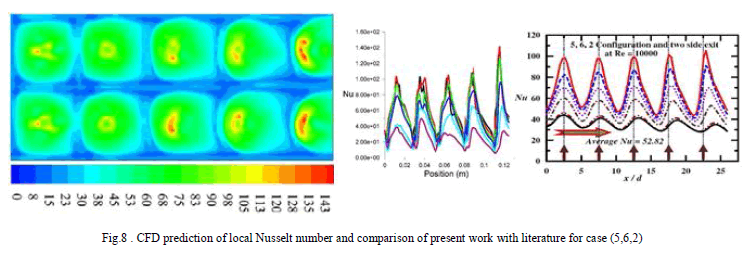
| Local distribution of Nusselt numbers for (5, 2), (5, 4) and (5, 6) configurations at their respective spanwise locations from y/yn = 0 to 0.5 in steps of 0.1 for the channel heights z/d = 1, 2 and 3 are shown in the fig. (1) – (9). The mean jet Reynolds number of 10000 is maintained for all the cases. It is observed that, for all configurations investigated, Nusselt number along all the lines from y/yn = 0 to 0.5 peaks first at x/d = 2.5, the location that corresponds to centreline of first spanwise row of jets, that are least influenced by the crossflow.For (5, 2) configuration, from fig. (1) - (3), peak values are observed to increase with increase in channel heights at all y/yn. The variation in stagnation Nusselt number can be attributed to increase in the jet Reynolds number values for this row of jets with increase in the channel heights. Peak values along y/yn = 0 are pushed downstream from the respective jet centrelines. Also, as a result of intense wall jets interaction, secondary peaks are formed. |
 |
| The local Nusselt number for z/d = 1 decrease in the fourth row, then increases in the fifth row. The decrease is attributed by the deflection of jet due to higher crossflow mass flux. But, the jet Reynolds number in the fifth row is as high such that, it overcomes the effect of crossflow and gives higher value of local Nusselt number. As it can be seen from the plot, it is almost equal to the highest peak in this case. Also the width of local Nusselt number band is very high due to high crossflow. The average Nusselt number for this case is found to be 45.667.For the case z/d = 2 and 3, the local Nusselt number decreases in the last two rows. It can be seen from the fig. that, the final rise in the local Nusselt number for the case z/d = 2 is because of, most part of the jet in the fifth row exits without hitting the plate. In z/d = 3 case, the final jet leaves without hitting the plate. Hence, no fifth peak is observed. The average values of Nusselt number for these cases are 42.927 and 40.471 respectively.A decreasing trend of average Nusselt number |
 |
| with increase in channel height is observed for this configuration.Nusselt number along all the lines from y/yn = 0 to 0.5 peaks first at x/d = 2.5, the location that corresponds to centreline of first spanwise row of jets, that are least influenced by the crossflow.For (5, 2) configuration, from fig., peak values are observed to increase with increase in channel heights at all y/yn. The variation in stagnation Nusselt number can be attributed to increase in the jet Reynolds number Local distribution of Nusselt numbers for (5, 2), (5, 4) and (5, 6) configurations at their respective spanwise locations from y/yn = 0 to 0.5 in steps of 0.1 for the channel heights z/d = 1, 2 and 3 are shown in the fig. The mean jet Reynolds number of 10000 is maintained for all the cases. It is observed that, for allconfigurations investigated. values for this row of jets with increase in the channel heights.In the downstream, all thespanwise rowofjets experience crossflow of spent air from upstream jets. Peak values alongy/yn = 0 are pushed downstreamfrom the respective jet centrelinesfourth row, then increases in the fifth row.As it can be seen from the plot, it is almost equal to the highest peak in this case. Also the width of local Nusselt number band is very high due to high crossflow. The average Nusselt number for this case is found to be 45.667. |
 |
| For the case z/d = 2 and 3, the local Nusselt number decreases in the last two rows. This indicates the dominance of crossflow over jet-flow in this region. It can be seen from the fig. that, the final rise in the local Nusselt number for the case z/d = 2 is because of, most part of the jet in the fifth row exits without hitting the plate.In z/d = 3 case, the final jet leaves without hitting the plate. Hence, no fifth peak is observed. The average values of Nusselt numberfor these cases are 42.927 and 40.471 respectively. A decreasing trend of average Nusselt number with increase in channel height is observed for thisconfiguration.Nusselt number along all the lines from y/yn = 0 to 0.5 peaks first at x/d = 2.5, |
 |
| the location that corresponds to centreline of first spanwise row of jets, that are least influenced by the crossflow.For (5, 2) configuration, from fig., peak values are observed to increase with increase in channel heights at all y/yn. The variation in stagnation Nusselt number can be attributed to increase in the jet Reynolds number Local distribution of Nusselt numbers for (5, 2), (5, 4) and (5, 6) configurations at their respective spanwise locations from y/yn = 0 to 0.5 in steps of 0.1 for the channel heights z/d = 1, 2 and 3 are shown in the fig. The mean jet Reynolds number of 10000 is maintained for all the cases. It is observed that, for allconfigurations investigated. values for this row of jets with increase in the channel heights.In the downstream, all thespanwise rowofjets experience crossflow of spent air from upstream jets. Peak values alongy/yn = 0 are pushed downstreamfrom the respective jet centrelines, the location that |
 |
| corresponds to centreline of first spanwise row of jets, that are least influenced by the crossflow.For (5, 2) configuration, from fig., peak values are observed to increase with increase in channel heights at all y/yn. The variation in stagnation Nusselt number can be attributed to increase in the jet Reynolds number Local distribution of Nusselt numbers for (5, 2), (5, 4) and (5, 6) configurations at their respective spanwise locations from y/yn = 0 to 0.5 in steps of 0.1 for the channel heights z/d = 1, 2 and 3 are shown in the fig. The mean jet Reynolds number of 10000 is maintained for all the cases. It is observed that, for allconfigurations investigated. values for this row of jets with increase in the channel heights.In the downstream, all thespanwise rowofjets experience crossflow of spent air from upstream jets. Peak values alongy/yn = 0 are pushed downstreamfrom the respective jet centrelines. |
 |
| Also, as a result of intense wall jets interaction, secondary peaks are formed. The local Nusselt number for z/d = 1 decrease in the 42.927 and 40.471 respectively. A decreasing trend of average Nusselt number with increase in channel height is observed for this configuration.For the case z/d = 2 and 3, the local Nusselt number decreases in the last two rows. This indicates the dominance of crossflow over jet-flow in this region. It can be seen from the fig. that, the final rise in the local Nusselt number for the case z/d = 2 is because of, most part of the jet in the fifth row exits without hitting the plate. In z/d = 3 case, the final jet leaves without hitting the plate. Hence, no fifth peak is observed. |
| The average values of Nusselt number for these cases are 42.927 and 40.471 respectively. A decreasing trend of average Nusselt number with increase in channel height is observed for this configuration.For the case z/d = 2 and 3, the local Nusselt number decreases in the last two rows. This indicates the dominance of crossflow over jet-flow in this region. It can be seen from the fig. that, the final rise in the local Nusselt number for the case z/d = 2 is because of, most part of the jet in the fifth row exits without hitting the plate. In z/d = 3 case, the final jet leaves without hitting the plate. Hence, no fifth peak is observed. The average values of Nusselt number for these cases are 42.927 and 40.471 respectively. |
 |
| For (5, 4) configuration, peak values are observed to increase with increase in channel heights at all y/yn which can be seen from the fig (4) – (6). Unlike (5, 2) configuration, we see five distinct peaks. Also, the shift of the peaks from their respective jet hole positions are less. This indicates that the crossflow is notas dominant because the crossflow mass flux is about half of that of in the case of (5, 2) configuration. For all three cases, the increase in local Nusselt number for first two rows is marginal. This is due to the fact that, the effect of increase in jet Reynolds number is nullified by the effect of crossflow.For z/d = 1 and 2, we see three sharp peaks at the end, for which the peak value increases in the direction towards exit. This is due to the increase in jet Reynolds number. |
 |
| The case z/d = 1 has the highest peak in this configuration. Because, for the last two rows the jet Reynolds number is higher than that of other configurations. Also, the line y/yn = 0.5 for z/d = 1 looks different from the other two configurations. The fluctuations diminish towards the exit. This is because the crossflow mass flux is higher than that of other two. Hence, most of the spent air are oriented along these lines as this is the path with minimum flow resistance. This attributes to the relatively smooth curve with slight increase in local Nusselt number with distance. The average Nusselt number for this case is 49.495.Whereas for the other two, the peaks are visible which indicates the crossflow effects are not appreciable in these regions and carries minimum local Nusselt number. For z/d = 3 case, the change in local Nusselt number for the first four peaks are marginal. This indicates that the effects of crossflow are cancelled out by the increase in jet Reynolds number. A steep peak is observed for the fifth row of jets which is due to the acceleration of wall jet towards the exit. The average values Nusselt number for these cases is 49.003 and 48.663 respectively. A decrease in average Nusselt number with increase in channel height is observed in this configuration too. |
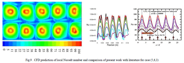 |
| The local Nusselt number contours and plots for the configuration (5, 6) are shown in the fig (7) – (9). It is observed that the shift of peaks from their respective hole location is very less because of very less crossflow. It is seen than the contour and plots of (5, 6, 1) are very similar to that of (5, 4, 1). It is because that the crossflow effects and jet Reynolds number variation are similar for this case. Although, as the jet Reynolds number varies not as much as the (5, 4, 1) case do, a decrease in the peak value is observed. The line y/yn = 0.5 is almost a smooth curve with slight increase in Reynolds number which is due to theorientation of spent air along this line. The average Nusselt number for this case is 45.625.For z/d = 2 configuration, at the location corresponding to first row of jets, a peak is observed which has higher value than that of the next three rows of jet. This is due to high jet Reynolds number and the decrease are attributed by the effects of crossflow even when there is a slight increase in jet Reynolds number. The peak due to last row of jets is high due to the combined effect of increase in jet Reynolds number and the acceleration of wall jet near exit. The average Nusselt number for this case is 44.421.The z/d = 3 configuration looks very different from all the other configurations. That is, all five peaks look similar and have almost same peak values. Also, the shift of peaks from its respective whole position is almost negligible as the crossflow mass flux is the lowest of all the other cases. Hence, jet-to-jet interaction is absent and the jet-to-crossflow interaction is negligible. Also the jet Reynolds number is almost equal to the mean jet Reynolds number. This is the case of single jet impingement. Hence, the array of jets may behave as if it is a single impinging jet. |
| The average Nusselt number for this case is 43.667. A decrease in value of average Nusselt number with increase in channel height is observed in this configuration too. In almost all the other cases, the local Nusselt number due to last row of impinging jets are the highest. But this case is an exception because, in all the other cases, due to crossflow effects, the jets are deflected.But for (5,6,3) case, since there is almost no crossflow, the impinging location of last row of jets is not as close that of in the other cases, hence the wall jet is not as much accelerated, resulting in lower value. The computational results obtained from this study are validated against the experimental results from the literature by Katti and Prabhu [2008]. It is observed that the local Nusselt number in the stagnation region is over-predicted in most cases. The lowest local Nusselt number is under-predicted. Also twin peaks at stagnation region are observed in the computational result, which is not present in the experimental data. However, its impact on average Nusselt number is low. The average Nusselt number is slightly under-predicted. |
CONCLUSION |
| Computational investigation is carried out to study the local heat transfer distribution on the target plate due to confined impingement of an in-line rectangular array of multiple jets with spent-air flow exiting in two opposite directions. The geometry is modelled in GAMBIT 2.4.6 software and meshed in the same. The solving and postprocessing is done on FLUENT 14 software. Streamwise pitch of 5d, spanwise pitch of 2d, 4d and 6d with channel heights of d, 2d and 3d are considered. Numbers of jets in the streamwise and spanwise direction are respectively 5 and 3 with the symmetry boundary condition being imposed on both X and Z directions, so as to replicate the experimental model in the literature. Mean jet Reynolds number of 10,000 is maintained. The results obtained are in very good agreement with the experimental data available in literature. The following conclusions are drawn from the study.For a given channel height, (5,4) configuration performs better. Closer spanwise spacing deteriorates the performance due to increased jet-to-jet interaction. The higher spanwise spacing results in lower value of local Nusselt number in the spanwise region between the jets, hence decrease in average value.For any spanwise configuration, z/d = 1 performs better. The higher average Nusselt number is achieved in this case due very high crossflow mass flux. Also, the jet Reynolds number in the streamwise direction increase, resulting in increase in peak values streamwise.Higher spanwise spacing and channel height as in the case of (5,6,3) exhibits single-jet impingement- like behavior, resulting in almost equal peak values and decrease in average Nusselt number. |
ACKNOWLEDGEMENT |
| The authors gratefully acknowledge Prof. Vadiraj Katti, Prof. S.V. Prabhu, Department of Mechanical Engineering, Indian Institute of Technology Bombay for permitting to use their experimental data for conducting this study. |
References |
|