ISSN ONLINE(2319-8753)PRINT(2347-6710)
ISSN ONLINE(2319-8753)PRINT(2347-6710)
Nitin Elish Daniel 1, Subrahmanya Swamy 2
|
| Related article at Pubmed, Scholar Google |
Visit for more related articles at International Journal of Innovative Research in Science, Engineering and Technology
Boring, also called internal turning, is used to increase the internal diameter of the hole. During most deep hole boring operations —4× length to diameter and greater—the enemy is chatter. It seems to show up sporadically, and the deeper the bore the worse it can be. Chatter results from vibration between the tool tip and workpiece interface. It is further increased by deep hole boring because as the length to diameter ratio of the boring bar increases. Thus, instead of smoothly lifting and breaking a chip, the tool tip vibrates, causing the chatter to appear on the workpiece surface. This is bad for jobs requiring tight dimensional accuracy. Here the resonating peaks and the mode shapes of the boring bar at these peaks have been found out. In this paper boring bars have been designed to exhibit chatter, and resonating peaks have been recognised, mode shapes at these peaks have been extracted
Keywords |
| Modal Analysis, Harmonic Analysis, Solid Boring Bar, Hollow Boring Bar, Finite Element Analysis, Mode shapes |
I. INTRODUCTION |
| Firstly the boring bars were designed for length to diameter ratio of 6, so as to exhibit chatter using CATIA platform and then the designed bars were imported into ANSYS platform where material constants were applied and then the model was meshed using 10 node solid 92, 10 node solid 92 was selected as it has a quadratic displacement behaviour and is well suited to model irregular meshes. The element is defined by ten nodes having three degrees of freedom at each node that is translations in the nodal x, y, and z directions. Then modal analysis was performed on these bars. First 50 mode shapes were extracted. Harmonic analysis was also performed on these bars, with a load at the cutting tip of 100 units. |
| Extensive research has been devoted to the characterization, modelling, and control of vibrations that occur when machine tools operate at the limit of their dynamic stability. These vibrations, known as machine-tool chatter, must be avoided to maintain machining tolerances, preserve surface finish, and prevent tool breakage. To avoid chatter, machine tool users limit material removal rates in order to stay within the dynamic stability boundary of their machines. From a manufacturing stand point, chatter is a constraint on the machine-tool user that limits the available production capacity. Thus, vibration-control methods for extending machine-tool operating envelopes are highly desirable. Machining by metal cutting is one of the most popular manufacturing techniques. High Material Removal Rate (MRR) and surface quality are always the primary objectives of machining operations. Since the 19th century industrial revolution, continuous improvements have been made in machine tools and cutting tools. New materials and designs have significantly improved the hardness and life of cutting tools. High speed machining centres can now operate at spindle speeds as high as half a million revolutions per minute (rpm). In order to utilize the power and capacity of these new machine tools and cutting tools, and to achieve high potential MRR and desired surface quality, optimum machining parameters are necessary. |
| In metal cutting manufacturing, a block is converted into a final product by removing extra material through turning, drilling, milling, broaching, boring and grinding operations performed by machine tools. Metal removal technologies are progressing in parallel with developments in materials, computers and sensors and have become one of the most widely used manufacturing processes to produce the final shape of products. |
| In the present manufacturing industry, line-boring process plays an important role in surfacing drilled holes. Some examples include automobile engines, fabrication of moulds, hollow circular structures. In this process, a horizontal boring bar with cutting tip mounted on it is inserted into the block and then centred in the main bearing or cam bearing bores with support bushings or fixturing. The bar is then turned and advanced to shave metal off the inside of the bores, thus the internal diameter (ID) of the bores can be resized to the desired dimensions (back to standard size or to oversize). For certain machine tool work piece combination, the main factors that influence the removal rate are the spindle speed, the depth of cut (axial and radial) and the feed rate. |
II. DESIGN OF BORING BARS |
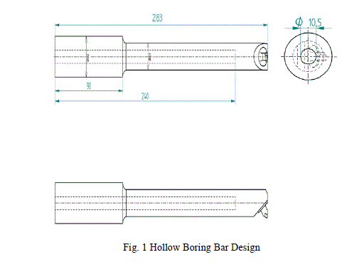
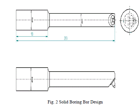
| Firstly the two boring bars, hollow and solid were designed for length to diameter ratio of 6, so that they exhibit chatter, the hollow and solid boring bar designs are shown in Figures 1 and 2 respectively. |
 |
III. MODAL AND HARMONIC ANALYSIS |
| The analysis parameters which were used for performing modal and harmonic analysis are given in this section. The element type used, constraints used, loads applied and material constants used are given as follows: |
| 1. The element type used is 10 node solid 92, solid 92 has a quadratic displacement behaviour and is well suited to model irregular meshes. The element is defined by ten nodes having three degrees of freedom at each node: translations in the nodal x, y, and z directions. |
| 2. Constraints used were zero degree of freedom constraints in x, y and z directions applied to all the nodes on the holding section of the bar. In case of harmonic analysis a force of 100 units was applied at the cutting end of the bar. |
| 3. The following material constants were used: |
| Young’s Modulus (E)=2.1×10⁵N/mm2 |
| Density (ρ)=7.874×10⁻⁶Kg/mm3 |
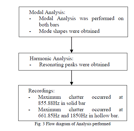
| To the designed model above three steps were applied then following analysis were performed : |
 |
IV. MODAL ANALYSIS RESULTS |
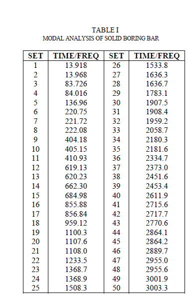
| 1. For modal analysis firstly the designed boring bars were imported into Ansys platform, to these models density of 7.874×10⁻⁶Kg/mm3 was applied, and a young’s modulus of 2.1×10⁵N/mm2 was applied. Once these material constants were applied, the models were meshed using 10 node solid 92 elements. This element was selected because it has a quadratic displacement behaviour and is well suited to model irregular meshes. Constraints used were zero degree of freedom constraints in x, y and z directions applied to all the nodes on the holding section of the bar. In case of harmonic analysis a force of 100 units was applied at the cutting end of the bar. Modal analysis result of solid boring bar is shown in Table I. Similarly modal analysis was also performed on hollow boring bar; its results are shown in Table II. |
 |
 |
 |
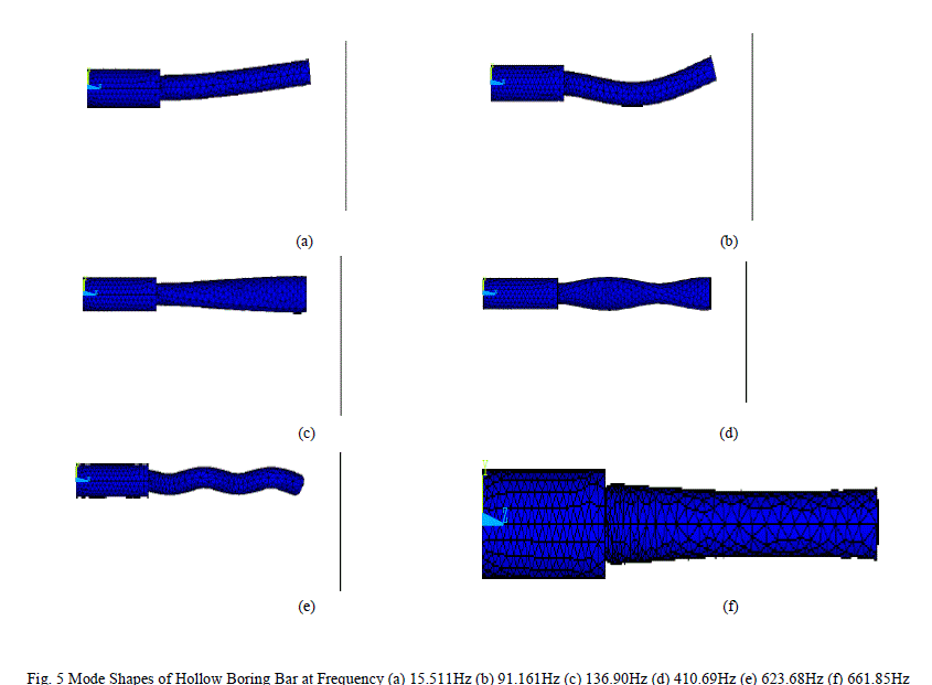 |
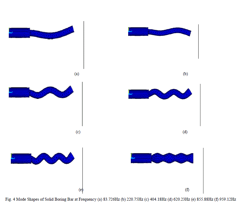
| Above Figures show the results of modal and harmonic analysis. The mode shapes obtained after performing modal analysis for solid bar are shown in Figure 4, these are the mode shapes extracted for points at which there is maximum resonance in solid boring bar. Similarly Figure 5 shows mode shapes extracted at points of maximum resonance for hollow bar. Figure 6 (a) shows harmonic analysis result of solid boring bar. It can be seen that resonating peaks occur at 83.726Hz, 220.75Hz, 404.18Hz, 620.23Hz, 855.88Hz, 959.12Hz, 1100.3Hz and so on. Figure 6 (b) shows harmonic analysis result of hollow boring bar. Here it can be seen that resonating peaks occur at frequencies 15.511Hz, 91.161Hz, 410.69Hz, 661.85Hz, 843.97Hz and so on. |
VI. CONCLUSION |
| It can be observed that from the analysis that the resonating peak at 855.88Hz is eminent in solid boring bar. In case of hollow boring bar the peaks at 661.85Hz and 1850Hz are eminent. Thus chatter is maximum at a frequency of 855.88Hz in solid boring bar, while in hollow boring bar maximum chatter is exhibited at a frequency of 661.85Hz and 1850Hz. |
References |
|