ISSN ONLINE(2319-8753)PRINT(2347-6710)
ISSN ONLINE(2319-8753)PRINT(2347-6710)
R.Lakshmi1, K.Rajan2
|
| Related article at Pubmed, Scholar Google |
Visit for more related articles at International Journal of Innovative Research in Science, Engineering and Technology
This paper deals with comparison of two switch and three switch Interleaved Forward Converters. The DC input is converted into high frequency AC using Forward Converter. The AC is rectified using half-wave rectifier. The ripple in the output is filtered using LC filter. The peak to peak ripple in the output of the DC-DC converter system with LC filter is compared with that of π filter system. Output powers of the two converters are also measured to identify a converter with better performance
Keywords |
| Interleaved Forward Converter, DC-DC Converter, Matlab, Microcontroller. |
INTRODUCTION |
| Many industrial applications require DC power. A DC to DC converter is an Electronic Converter which converts a source of Direct Current (DC) from one voltage level to another. DC to DC converters (with isolation) convert one DC voltage level to another, by storing the input energy temporarily and then releasing that energy to the output at a different voltage level. The energy can be stored in the magnetic field storage components (inductors, transformers) or electric field storage components (capacitors). This conversion method is more efficient than linear voltage regulation which dissipates unwanted power as heat. The efficiency is increased by the use of power FETs, which operates at high frequency than power bipolar transistors. DC to DC converters are important in portable electronic devices such as cellular phones and computer which are supplied with power from batteries. Galvanic isolation is the principle of isolating functional sections of electrical system by preventing the moving of the charge carrying particles from one section to another, i.e. there is electric current flowing directly from one section to the next. Energy and/or information can still be exchanged between the sections by other means e.g. capacitance, inductance electromagnetic waves, optical, acoustic or mechanical means. Such a principle is used in these DC to DC converters (with isolation). Two types of converter with galvanic isolation are Flyback converter and Forward converter. Forward converter is a popular switched mode power supply (SMPS) circuit that is used for producing isolated and controlled DC voltage from the unregulated DC input supply. Applications of this forward converters are Power supply for DC motor, Battery charging, Battery operated Electric vehicle, Telecom applications etc. |
II. RELATED WORK |
| Analysis and design of forward converter with energy regenerative snubber is given by Smedley (2010). Design of high efficiency flyback converter with energy regenerative snubber is given by Liao (2008). An efficient active LC snubber for forward converters is given by Jinno (2009). A novel integrated non-dissipative snubber for flyback converter is given by Ai (2005). Wide range dual switch forward-flyback converter with symmetrical RCD clamp is given by Wei (2005). Transformerless double-conversion UPS using a regenerative snubber circuit is given by Reinert (2009). Spike suppression method of bidirectional high frequency inverter using a regenerative snubber is given by Ramli (2004). Efficiency improvement for SR forward converters with LC snubber is given by Jinno (2001). A new interleaved series input parallel output (ISIPO) forward converter with inherent demagnetizing features is given by Taotao (2008). The above literature does not deal with comparison of two switch and three switch interleaved forward converter. This work aims to find a better converter of the two converters considered. The input DC supply for a forward converter is often derived after rectifying the AC voltage. The forward converter, when compared with the flyback circuit is generally more energy efficient and is used for high power output applications (in the range of 100 watts to 200 watts). Whereas, the flyback converter used for low power application below is 100 watts. The forward converter is simple and retains many features of the buck converter. With a proper choice of the transformer turns ratio, the forward Converter can attain wide step down voltage which is useful for offline applications. Moreover, this forward converter is quite easy to control. These advantages make the forward converter for low to medium isolated offline power applications. The scope of this paper is as follow: Second section deals with forward converter. The simulation results are given in the third section. Fourth section deals with the conclusion. |
III. FORWARD CONVERTER |
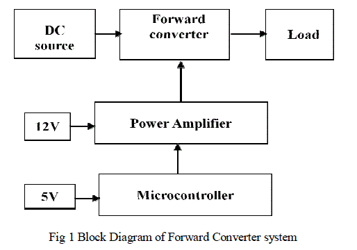
| The block diagram of forward converter system is shown in Fig1. This converter converts unregulated DC power to regulated DC power. It contains high frequency transformer which is also called isolation transformer. This provides isolation between load and main circuit. As the frequency increases, the size of the transformer decreases. Since the flux decreases with the increase in the frequency of the transformer. |
 |
| 3.1 DC LOAD |
| The output power is regulated DC power which can used for applications like speed control of the motor, battery charging, telecommunication, computers, cellular phones, electrical drives and other applications which needs DC power. |
| 3.2 MICROCONTROLLER |
| Microcontroller is used to generate triggering pulse for MOSFET. The triggering pulses are of same width and have equal interval of time. Microcontroller is also used to control the output of forward converter by varying the pulse width applied to the MOSFET. Microcontrollers have more advantages compared to the analog circuits like fast response, low cost, small size and improved relaibility etc. |
| 3.3 POWER AMPLIFIER |
| Power amplifier is used to amplify the pulses produced by microcontroller and give the amplified pulse to the MOSFET in the main circuit. It also provides isolation between the microcontroller and the power circuit. It is neccessary to provide isolation between the power circuit (main circuit) and microcontroller. Power amplifier operates at 12V which is obtained from the AC main using a step down transformer and rectifier. |
IV. SIMULATION RESULTS |
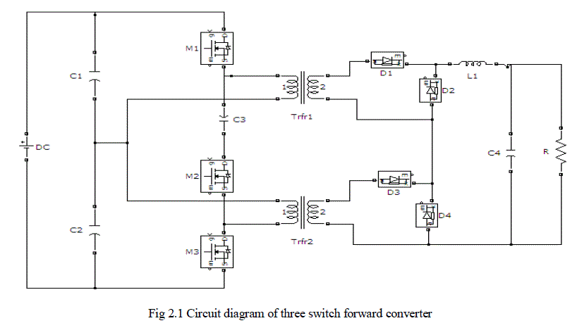
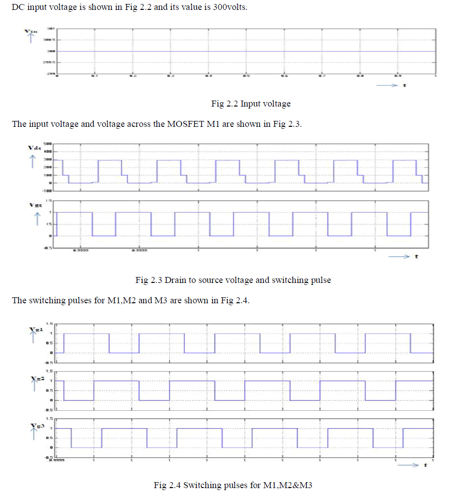
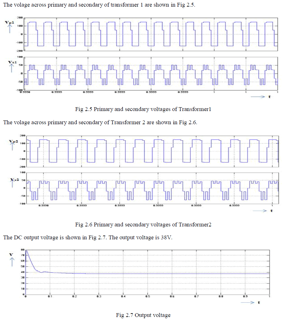
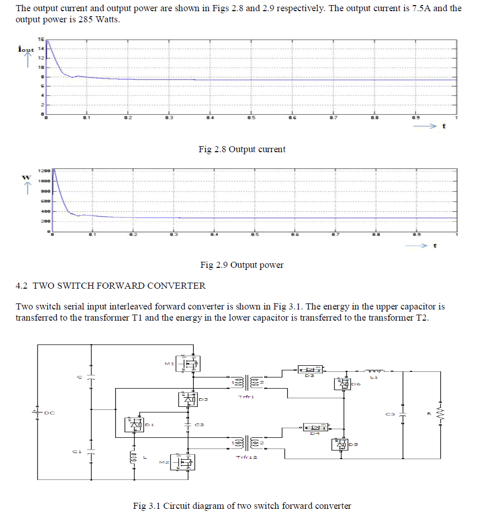
| The simulink model for three switch DC-DC converter is shown in Fig 2.1. The scopes are connected to measure output voltage and output current. The output power is obtained by multiplying the output voltage and the output current. |
| 4.1 THREE SWITCH FORWARD CONVERTER |
| The energies in the transformer secondaries are added and temporarily stored in the LC filter and then it is released to the load. |
 |
 |
 |
 |
 |
 |
 |
 |
V. CONCLUSION |
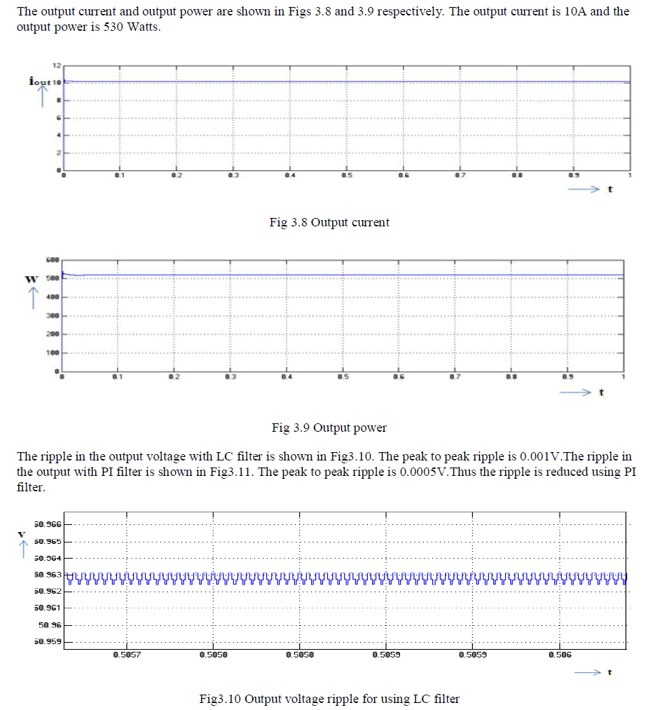
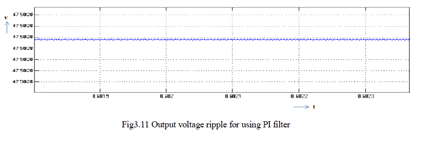
| The two switch and three switch serial input interleaved forward converters are modeled and simulated using MATLAB Simulink and the results are compared. The output of two switch converter system is higher than that of three switch converter system. The ripple in the output with π filter is less than that with LC filter. The simulation results are in line with the predictions. The contribution of this work is to identify suitable converter for DC-DC conversion. |
| The disadvantages of three switch converter are that it needs three controlled switches and two transformers. The scope of this work is the design and simulation of open loop controlled interleaved forward converter system. The simulation of closed loop system will be done in future. |
References |
|