ISSN ONLINE(2319-8753)PRINT(2347-6710)
ISSN ONLINE(2319-8753)PRINT(2347-6710)
Tamilselvan.R1, Suganya.P2, Rengarajan. N 3
|
| Related article at Pubmed, Scholar Google |
Visit for more related articles at International Journal of Innovative Research in Science, Engineering and Technology
The global electrical energy consumption is rising and there is steady increase of the demand on power generation. In addition to conventional power generation units a large number of renewable energy units are being integrated into the power system. The Wind Energy Conversion system (WECS) is the most cost competitive of all the environmentally clean and safe renewable energy sources in world. Doubly fed induction generator (DFIG) based wind farm is today the most widely used concept. In this paper, Artificial Neural Network (ANN) control technique has been developed for Doubly Fed Induction Generator (DFIG) based wind energy generation system. With the increasing use of wind power generation, it is required to instigate the dynamic performance analysis of Doubly Fed Induction Generator under various operating conditions. In this paper, two control techniques have been proposed, the first one is using PI controller and the second one is based on ANN. The performance of the proposed control techniques is demonstrated through the results. From the results it is observed that the dynamic performance of the DFIG is improved with the ANN control technique
Keywords |
| Wind power generation, Direct current Control, Neural networks, DFIG, Growing neural network, WECS. |
INTRODUCTION |
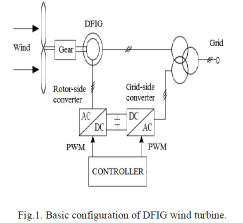
| Considering the extent of industrialization these last decades, the demand for electrical energy became very important has as a consequence the reduction in world hydrocarbon stock. Face to that and with the challenge of the climate warming of the ground caused by the emissions of gases to greenhouse effect related to the excessive use of energy of origin fossil matters, it proves to be necessary to call upon new energy sources which will be without consequence for the human being and the environment. Thus the industrialized countries within the framework of the protocol of Kyoto launched out in the development and the use of the renewable energy sources like the solar one, the biomass, geothermic, hydraulics. Among these energy sources, the wind energy represents a rather important potential not to replace existing energies but for bearing with the damping of the request more and more which gallops. After centuries of evolution and the search more pushed for a few decades, several countries today have resolutely turned to wind energy. One of the current axes of search is the generation of electrical energy using doubly fed induction machine, using like means of drive wind energy. Integrated in a wind system, the DFIG makes it possible to function on a broad range speed of wind, and to extract from it the maximum of power possible for each speed of wind. Its stator circuit is connected directly to the grid. A second circuit placed at the rotor is also connected to the network but via power converters (Fig.1). Since the forwarded rotor power is less, the cost of the converters is some reduced in comparison with a wind generator at variable speed fed with the stator by power converters. |
| It is the reason for which one finds this device for the production in strong power. In this paper, the control of electrical power exchanged between the stator of the DFIG and the power network by controlling independently the torque (consequently the active power) and the reactive power is presented. Several investigations have been developed in this direction using cyclo-converters as converters and classical proportional-integral regulators. In our case, after modelling the DFIG and choosing the appropriate d-q reference frame, the rotor is supplied by an inverter on two levels controlled by PWM (Pulse width Modulation) technique. The active and reactive powers are controlled using respectively Proportional- Integral (PI) and an NN controller. Their performances are compared in terms of reference tracking and robustness against machine's speed electromagnetic torque and constant Dclink voltage. |
BASIC CONCEPTS OF WIND TURBINE |
| Wind turbine converts the kinetic energy of the wind into mechanical energy [10]. The wind power developed by the turbine is given by the equation |
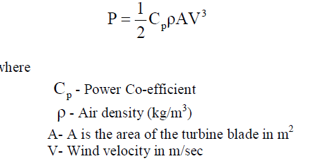 |
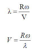
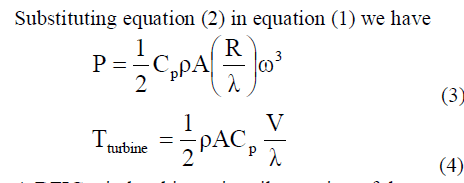
| The power Co-efficient CP gives the fraction of Kinetic Energy of the wind that is converted in to mechanical energy by the wind turbine. It is a function of the tip speed ratio (λ) and depends on the blade pitch angle for pitch – controlled turbines [14]. The tip speed ratio may be defined as the ratio of linear speed of turbine blade and the wind speed. |
 |
 |
| A DFIG wind turbine primarily consists of three parts: |
| Wind turbine drive train, an induction generator, and a power electronic converter. In the wind turbine drive train, the rotor blades of the turbine catch wind energy that is then transferred to the induction generator through a gearbox. The induction generator is a standard, wound rotor induction machine with its stator windings directly connected to the grid and its rotor windings connected to the grid through a frequency converter. The frequency converter is built by two self- commutated voltage source converters, viz. the rotor side converter (RSC) and the Grid side converter (GSC), with an intermediate DC-link voltage. |
| The DFIG can be operated in two modes of operation namely sub-synchronous and super-synchronous modes depending on the rotor speed, below and above the synchronous speed. Figure.1 shows the basic scheme adopted in the majority of systems. The stator is directly connected to the AC mains, whilst the wound rotor is fed from the Power Electronics Converter via slip rings to allow DIFG to operate at a variety of speeds in response to changing wind speed. Indeed, the basic concept is to interpose a frequency converter between the variable frequency induction generator and fixed frequency grid [11]. The DC capacitor, linking stator and rotor-side converters allows the storage of power from induction generator for further generation. To achieve full control of grid current, the DC-link voltage has to be maintained at a constant value. |
 |
| The control strategy of the Rotor Side Converter (RSC) aims, at first, to extract maximum power under fluctuating wind speed. The fuzzy logic controller used for controlling the real and reactive power flow can be improved while using a cross coupled controller to adjust the speed and power of the system. An overall control scheme can be implemented in the MATLAB simulink platform. The control level of DFIG performs the operation of the rotor side and the grid-side back-to-back converters. The rotor side controller will perform the task of real and reactive power flow, track the optimum power point and limit the power during high wind speed [16]. The grid side controller keeps the constant DC voltage to the system and injecting the reactive power to the grid [10]. There will be two control loops which can use the integrated proportional controller that can be simulated using Matlab/simulink platform. The fuzzy logic controller can be tuned with direct current d-q vector control and real and reactive power flow can be improved while using a cross coupled controller to adjust the speed and power of the system. |
CONVENTIONAL AND DIRECT-CURRENT VECTOR CONTROL DESIGN |
| In a DFIG wind turbine, the GSC controls the dc-link voltage and contributes to the reactive power or grid voltage support control of the overall DFIG system as well. |
| (i) GSC Transient and Steady- State Models |
| Fig. 2 shows the GSC, in which a dc-link capacitor is on the left and a three-phase voltage source is on the right. |
| The d-q reference frame, the voltage balance across the grid filter is |
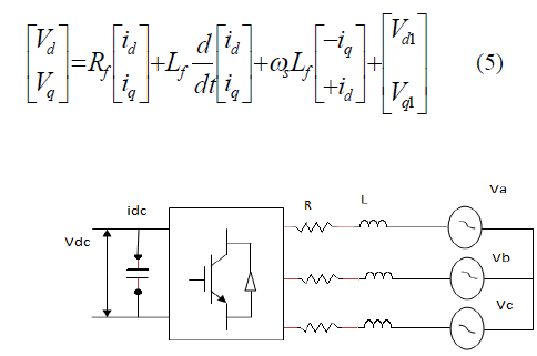 |
| Fig 2 Grid-connected converter |
| Were ωs is the angular frequency of thee Point of common coupling voltage and Lf and Rf are the inductance and resistance of the grid filter. Where Vdq, Idq, and Vdq1 stand for steady state space vectors of point of common coupling voltage, grid current, and converter output voltage. |
 |
| In the PCC voltage oriented frame [2] , [17], the instant active and reactive powers absorbed by GSC from the grid are proportional to grid d-axis and q-axis currents as shown in the below equation (4) and (5). |
 |
| (ii) Direct current control Mechanism |
| The conventional vector control method for the for the direct current has a nested control loop structure for controlling the grid side current as shown in the figure. In which the d-axis is used for the DC-link voltage and q-axis is used for the reactive power control. The output of the controller is a d-axis or q-axis current loop controller. This tuning current is different from the actual measured d-axis or q-axis current. It is necessary to point out a fast currentloop controller is to assure the highest power quality in terms of harmonics and unbalance for the grid side controller [14]. The overall control structure for the grid side controller is show in the controller Fig.3. The PI part of the controllers operates on a direct target control principle. The PI parameters mainly based on the error e, between the controlled variable and its target value and the change in error [15]. The initial value of the PI current control loop is tuned according to the error reducing principle. |
| (iii) Rotor side control DFIG speed and reactive power control |
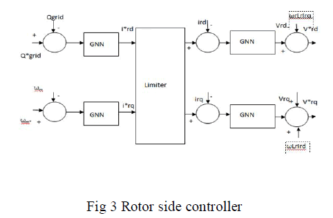 |
| The rotor side controller controls the induction generator of a DFIG wind turbine for energy extraction from the wind and coordinates with the GSC for reactive power or grid voltage support control through nested loop structure. The importance of the rotor side control loop is to assure the highest power quality in terms of harmonics and unbalance for the DFIG [4]. |
| The direct current vector control mechanism is not used because the rotor electrical frequency is near zero around the synchronous speed. In the figure the speed reference is generated according to the maximum power extraction principle [3]. |
 |
| It is found that there is some drawbacks while using PI controller in RSC for extracting the maximum wind speed, the control of real and reactive power also have draw backs and the dc-link voltage is also not maintained constant this are all the major drawbacks we found in this paper to overcome this draw back we are introducing here the neural network based RSC for controlling the rotor current and to overcome all the above draw backs is shown in figure 3.The slip power which is extracted from the rotor also can be improved by placing a boost converter and improves the slip power which is extracted from the rotor and it is given to the grid through common dc link voltage. |
| (iv) Growing neural network based RSC |
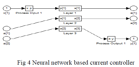
| The neural network has the capability to control nonlinear uncertain and adaptive systems with parameter variation. Neural network control needs the mathematical formulation to reduce the error by back propagation algorithm. In this paper growing neural network control is associated with vector current control method to generate the value speed of the rotor side controller which ensure the precision and robustness of the control of speed, real and reactive power of DFIG. For a given wind speed the aim is to achieve the maximum power extraction is to regulate the turbine rotating speed to an optimal speed so that the maximum power can be captured from the wind. The maximum wind speed in the turbine can be achieved by taking the shaft speed and generator speed the growing neural network controller controls the turbine to achieve the maximum power from the wind speed. The back propagation algorithm has been used for reducing the error in the speed. It reduces the error until the maximum power extraction point has been reached is shown in figure 4. |
 |
| (v) Slip power improvement |
| The 30% of the slip power has extracted from the rotor which has been improved by placing boost converter. The extracted power in rotor has been fed to the boost converter and it is given to the grid via a common dc-link. So the power which we are extracting from the wind mill has been improved in the grid side. |
| (vi) Real and Reactive power control |
| The grid side control contributes the reactive power control. In the direct current control configuration the GSC contributes a part of the reactive power control mainly the rotor side control contributes majorly due the extraction of maximum power from the wind turbine is based on RSC. In conventional control configuration the reactive power is not controlled fully in proposed method we are introducing growing neural network based controller for the rotor side which controls the reactive power and real power. The real power is also improved effectively 40% compared to conventional method which results in reduced oscillations compared the conventional control techniques. |
EVALUATION AND COMPARISON |
| To evaluate and compare the peak power tracking, reactive power reactive power, grid voltage support, real power flow to the grid, and the power factor values for the various wind speed has been estimated and compared with the convention control techniques. |
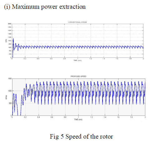 |
| The speed of the rotor has been compared for both the PI controller based control and the growing neural network based control. In PI based rotor controller it has estimated the rotor speed ranges 750 rpm which lags 50% compared to the proposed control it results in 1480 rpm. So the maximum wind power has been estimated while we are using growing neural network controller. The neural network based controller shows better performance compared to conventional control technique as shown in the figure 5. |
| (ii) DC-link voltage |
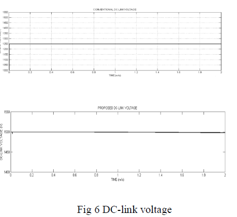 |
| The Dc-link voltage value has been compared for both the PI controller based control and the growing neural network based control. In PI based controller it has estimated the value of dc link voltage reduces to 1250V which lags 20% compared to the proposed control it results in1500V. So the DC-link voltage value has been maintained constant while we are using growing neural network controller. The neural network based controller shows better performance compared to conventional control technique as shown in the figure 6. |
 |
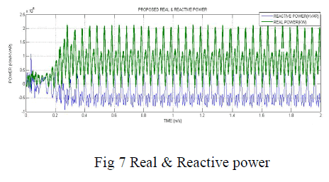 |
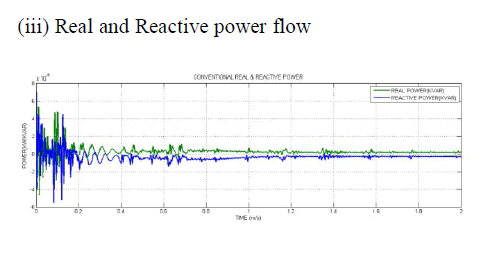
| The real and reactive power control has been compared for both the PI controller based control and the growing neural network based control. The neural network based controller shows better performance compared to conventional control technique as shown in the figure 7. |
| (iv) Power factor values for various wind speed |
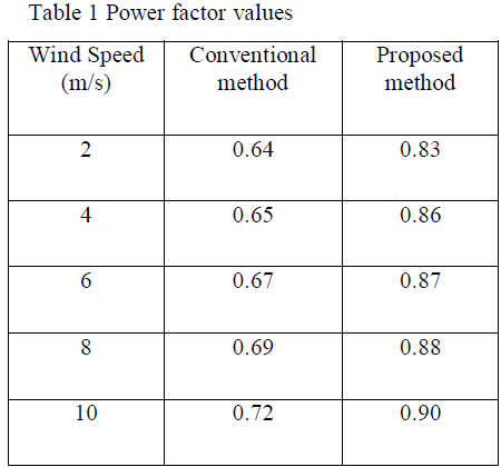
| The simulated power factor values has been shown in the table 1 for the various wind speed. |
 |
CONCLUSION |
| This paper has presented an analysis of DFIG-based wind turbine control study using a neural network based current vector control design. The paper evaluates and compares the proposed control scheme with the conventional standard DFIG control method. The paper shows that under direct-current vector control configuration, how the integrated GSC and RSC control is designed to implement the dc-link voltage, real power, reactive power, grid voltage support control functions. Comprehensive simulation studies demonstrate that the proposed DFIG wind turbine control structure can effectively accomplish wind turbine control objectives with superior performance under both steady and variable wind conditions within physical constraints of a DFIG system. Beyond physical constraints of a DFIG system, the proposed control approach operates the system by regulating the RSC for real and reactive power control and by controlling the GSC to stabilize the dc-link voltage as the main concern. The direct-current vector control structure is also effect for peak power tracking. Power factor values have been improved and grid voltage support control shows better performance while using growing neural network. |
References |
|