ISSN ONLINE(2319-8753)PRINT(2347-6710)
ISSN ONLINE(2319-8753)PRINT(2347-6710)
Dhiraj K. Bhandarkar1 and Sanjay P. Shekhawat2
|
| Related article at Pubmed, Scholar Google |
Visit for more related articles at International Journal of Innovative Research in Science, Engineering and Technology
In New Light commercial vehicle development, Engine is mounted at rear to have low Engine Noise and Vibration inside cabin. At the same time there is a need of high load carrying rear suspension to suit market requirement. In this paper complete design of leaf spring rear suspension for rear engine is discussed.This is nontraditional type of suspension with leaf spring application for rear engine vehicle. Traditionally, for light commercial vehicles, Engine is placed at front/middle giving huge space for traditional rear axle with differential inside. Design of rear suspension is verified and validated successfully for durability and handling by doing finite element analysis and testing.
Keywords |
| Rear suspension, Rear axle, Handling, finite element analysis. |
INTRODUCTION |
| Traditionally, for light commercial vehicles, Engine is placed at front/middle giving huge space for traditional rear axle with differential inside as shown in Fig 1. |
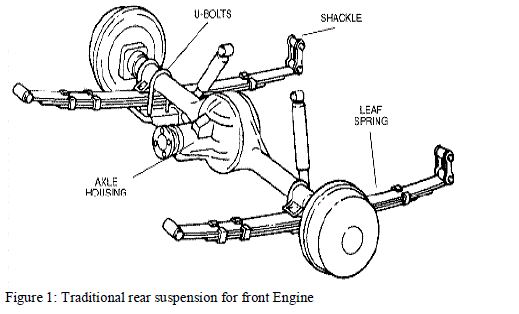 |
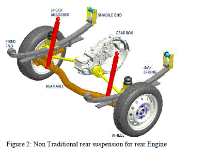
| Propeller shafts are used to transfer drive from power pack to axle housing. This paper describes complete design of non-traditional type of suspension with leaf spring application for rear engine vehicle as shown in Fig 2. In New Light commercial vehicle development, Engine is mounted at rear to have low Engine Noise and Vibration inside cabin. At the same time there is a need of high load carrying rear suspension to suit market requirement so necessary to use leaf spring type rear suspension. |
LITERATURE REVIEW |
| Rajendran,et al[1] formulates technique using genetic algorithms (GA) for design optimization of composite leaf springs is presented here. The suspension system in an automobile significantly affects the behaviour of vehicle, i.e. vibration characteristics including ride comfort, directional stability, etc. Mahmood M Shokrieh,et al[2]i analysed using ANSYS V5.4 software. The finite element results showing stresses and deflections verified the existing analytical and experimental solutions. Hiroyuki Sugiyama et al [3] investigated a nonlinear elastic model of leaf springs is developed for use in the computer simulation of multibody vehicle systems. H.A. Al-Qureshi [4] has shown increased interest in the replacement of steel springs with fiberglass reinforced composite leaf springs. Fundamental properties of the dimensioning of the double tapered FRP leaf spring were investigated W.J. Yu,et al[5]. The optimal taper ratio was proved to be 0·5. M.A. Osipenkoet al[6] investigated the weak joint bending (unbonded contact without friction) of the stack of slim non-uniform curved beams (leaves) with rectangular cross-sections is considered. Dipendra Kumar Roy [6] presented study deals with the numerical analysis of large deflection of prismatic cantilever beams for various types of material properties with a transverse load at free end, to study the displacement response of leaf springs. J.P. Hou, et al[7] presented the design evolution process of a composite leaf spring for freight rail applications. Kaldas,et al[8] given due to the importance of the fast transportation under every circumstance, the transportation process may require a high speed heavy vehicle from time to time, which may turn the transportation process more unsafe. Liu, W.[9] elaborate the needs suspension and steering systems with different features to fit different driving conditions. Romero et al[10] proposed to measure the rollover propensity of road tankers when subjected to lateral perturbations derived from steering manoeuvres. The testing principle involves subjecting a scaled down sprung tank to the elimination of a lateral acceleration, to analyze its rollover propensity as a function of various vehicle’s operational and design parameters. Wasfy, T., et al[11] suggested a time-accurate finite element model for predicting the coupled dynamic response of tanker trucks and their liquid payloads is presented along with an experimental validation of the model. Ding, F.,et al[12] has proposed a new roll-resistant hydraulically interconnected suspension (HIS) system for a tri-axle straight truck with rear tandem axle bogie suspension to suppress the roll motion of truck body. Gordon, T. et al[13] determined the spatial and temporal distributions of vertical loads arising from heavy trucks driven on flexible bridge structures. Wagner, T.,. et al[14] describes the mechanical design of a Suspension Parameter Identification Device and Evaluation Rig (SPIDER) for wheeled military vehicles. This is a facility used to measure quasi-static suspension and steering system properties as well as tire vertical static stiffness. Mastinu, G.,et al[15], done a comprehensive research is presented aiming at assessing the ride comfort of subjects seated into road or off-road vehicles. Although many papers and books have appeared in the literature, many issues on ride comfort are still to be understood, in particular, the paper investigates the mutual effects of the posture and the vibration caused mostly from road unevenness. |
METHODOLOGY |
| Suspension design for rear engine, consist of following steps: |
| 1. Vehicle layout making: Rear suspension layout made by two point deflection method using 3 link mechanisms. Calculations are made to get front and rear suspension roll centres and corresponding roll axis. In this concept level stage, different suspension parameters like, spring stiffness and camber, spring mountings, bump stop stiffness etc. are fine-tuned and finalized. |
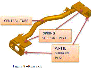
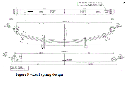
| 2. Rear axle design: Due to rear engine mounting, Engine is coming in between rear suspension making the design complicated. Considering all packaging constraints, rear axle is designed by bending center tube at offset position with wheel center. Spring design for target load and stiffness is also completed. |
| 3. Finite Element Analysis of Rear axle: Rear axle analysis done to get optimized size and thickness of different parts to withstand overloading. Initially analysis is done with complete vehicle model of rear axle, spring, spring bushes, frame etc. to get effect of leaf spring & bush stiffness on stress level of rear axle. Based on this, small reduced model is developed to make different iterations to design, cost effective rear axle with minimum time. |
| 4. Dynamic calculations: Weight transfer is calculated at turning for handling estimation. |
| 5. Design verification: Strain data at critical locations are acquired on proto type axle while vehicle running on different roads and track. Estimated stress levels and measured stress levels are found matching. Acceleration levels on axle and frame is acquired and found reasonably matching with calculated. |
| Details of each step are described in following sections. |
1. Design of Rear Suspension |
| Initial concept phase started with making Vehicle layout to finalized different suspension parameters. |
 |
2. Vehicle Layout Making |
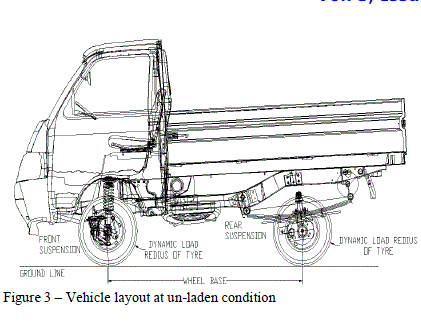
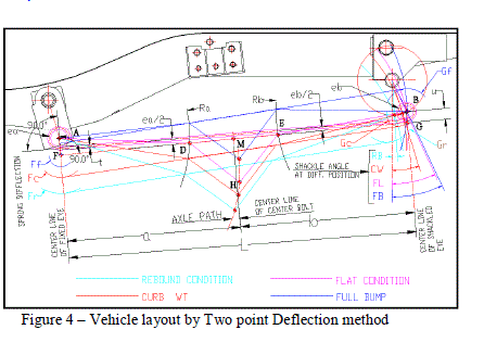
| First step done is finalized spring mounting location on frame, which further freezes wheel base and leaf spring length. Based on this wheel base, rear axle loads at different conditions like GVW, overload etc. is calculated. Semi Elliptical leaf spring is used for the layout as shown in Fig 3. This type of spring can be considered as two cantilever springs, and the resulting spring action can be determined by considering the spring as a three-link mechanism. Geometry of spring action, including wheel movement at different conditions and shackle effect is estimated by Two-Point Deflection Method layout for selected wheel displacements. |
3. Rear suspension layout by Two-Point Deflection Method |
| This method has the advantage that all the layout work can be done within the overall length of the spring. The unsymmetry factor is small so possible to use this method to construct the spring layout. |
| The principle of this method is based upon the use of the two cantilever deflections corresponding to a given deflation at the centre of the spring seat. These deflections may be computed for vertical positions of the spring seat, for maximum compression (metal-to-metal), curb weight and maximum rebound. When they are applied to the three-link equivalent of the spring with main leaf in the flat position, the path of the axle and the angle of the spring shackle can be determined entirely by constructing the layout as shown in Fig 4. |
| 4. Nomenclature- for above layout |
| a = Fixed cantilever length called “front” length e= Eccentricity =0.5(eye ID +t) |
| b= shackled cantilever length called “rear” length L= total spring length |
| u= Distance between points B and G Ff, Fc&Fr = Deflection of point F |
| Gf, Gc&Gr= Deflection of point G |
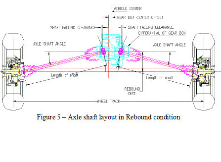
| During vertical movement of wheels, axle shaft will slide in and out inside differential housing which will causing shaft falling or hitting with differential pin. To resolve this problem axle shaft layout is made. |
| Axle shaft layout– The axle shaft layout made in the flat condition and decides the length of the shaft. To avoid shaft falling OR hitting with differential pin, axle shaft layout made at different vehicle condition i.e. Rebound, Curb weight and Full Bump condition as shown in Fig 5.Rebound occurs when the wheel hits a dip or hole and moves downwards. By using this layout we can get the axle shaft falling clearance with respect to gear box cage and maximum axle tilt angle. Curb weight condition happens when the vehicle loaded with its own curb weight. In this condition we will get the axle shaft falling clearance and shaft angle in curb wt. condition. Full Bump occurs when the wheel hits a bump & moves up. It is upward displacement of the axle relative to the body. By this layout we can get the axle shaft hitting clearance with respect to differential pin and axle tilt angle in full bump condition. |
 |
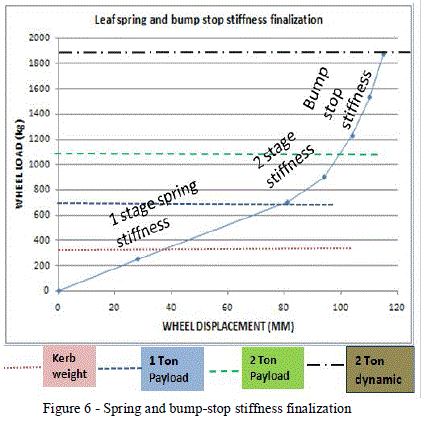
| Based on above studies, wheel vertical displacement is finalized which satisfies all the layouts. Now as load coming on single rear wheel at all conditions as well as wheel displacements are finalized, spring camber and bump stop height is finalized to have desired spring stiffness and bump stop stiffness as shown in Fig 6. This stiffness is further studied and fine-tuned by doing handling and ride comfort calculations. Detail design of spring, bump stop and rear axle are in following sections. |
 |
5. Rear Axle Design |
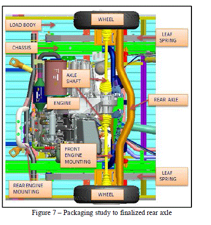
| Based on layouts and packaging studies as shown in Fig 7, centre distance between left and right spring and wheel mounting is finalized. Central tube is bend to avoid interface during vertical travel of axle. Tube axis also designs at offset position from wheel center line to have room for axle shafts. |
 |
 |
 |
DYNAMIC CALCULATIONS |
1. Handing calculations: |
| CAE is very effectively used for giving design input for finalizing the stiffness of Leaf Spring by doing dynamic calculations for vehicle handling capabilities. |
| Complete vehicle model as shown in Fig 17, is used to study dynamic behavior of the vehicle in rolling by giving lateral acceleration to the vehicle. |
 |
| Graph in Fig 18 show that, decrease in stiffness of rear leaf spring increases the vehicle roll for same value of lateral acceleration (keeping front suspension stiffness constant) also lateral acceleration at which side rear wheel leave road surface goes on increasing. Up to the stiffness of 120N/mm, one of the rear wheels will leave the rood surface when lateral acceleration reaches to its toppling value (1.3g); but below 120N/mm, at 80 N/mm, front wheel will leave the road surface at its toppling acceleration value (1.2g). |
| Based on Fig. 18, 120 N/mm is the best handling rear spring stiffness as it give highest lateral toppling acceleration (1.3 g) however slightly higher stiffness (160N/mm) is selected to reduce wheel vertical movement to avoid hitting of shaft with differential pin. |
2. Design Verification: |
| Strain gauges are pasted at critical locations and strain data are acquired Leaf spring at different events. Estimated stress levels and measured stress levels are found matching, which verify that input loading & boundary conditions taken in analysis are correct. |
RESULTS AND DISCUSSIONS |
 |
| Fig 19 shows, difference between analysis and actual (strain gauging) results are within 12% which is within acceptable limit. |
CONCLUSIONS |
| The aim of the project outlined in this paper was to a develop methodology to design Leaf spring rear suspension for rear engine. The challenges in designing leaf spring rear suspension for rear engine are different from those for front engine. This paper had given some of the difference and describes in detail unique design criteria due to packaging, axle movement etc, of leaf spring rear suspension for rear engine. With the use of Finite element analysis and Engineering codes, this challenging design was successfully completed. This paper gives methodology to use Finite element analysis not only for durability analysis but also for handling, ride comfort, optimization and test setup finalization. This gives advantage of completing optimized design in less time; as Design, verification get completed in short time. Hence total development cycle got compressed significantly. |
References |
|