ISSN ONLINE(2319-8753)PRINT(2347-6710)
ISSN ONLINE(2319-8753)PRINT(2347-6710)
P. Bharat Kumar1, P. Sujatha2 and K. S. R. Anjaneyulu3
|
| Related article at Pubmed, Scholar Google |
Visit for more related articles at International Journal of Innovative Research in Science, Engineering and Technology
This paper presents a robust controller design for a Brush less DC motor by using Quantitative Feedback Theory [1] and its comparison with different control techniques. The different types of controller design techniques for a Brush Less DC motor involves (i) Fuzzy logic controller (ii)Genetic Algorithm based controller (iii)QFT Controller. The design of QFT controller involves preparation of performance characteristics, selecting QFT boundaries, choosing the controller structure and pre-filter design. All the controllers have been designed and simulated to control the BLDC Motor. The proposed (QFT) control system is more efficient in improving the step response characteristics such as, reducing the steady-states error; rise time, settling time and maximum overshoot in speed control of a linear brushless DC motor.
Keywords |
| BLDC Motor, robust control, Quantitative Feedback Theory (QFT). |
INTRODUCTION |
| Brushless DC (BLDC) motors are one of the electrical drives that are rapidly gaining popularity, due to their high efficiency, good dynamic response and low maintenance. BLDC motors are used in industries such as Appliances, HVAC industry, medical, electric traction, road vehicles, aircrafts, military equipment, hard disk drive, etc. Comparing BLDC motors with DC motors, the DC motor have high starting torque capability, smooth speed control and the ability to control their torque and flux easily and independently. But in the DC motor, the power losses occur mainly in the rotor which limits the heat transfer and consequently the armature winding current density, while in BLDC motor the power losses are practically all in the stator where heat can be easily transferred through the frame, or cooling systems can be used specially in large machines. The time response characteristics of the BLDC Motor are observed and compared from the design of different controllers. The different types controller design techniques that are used for the speed control of Brush Less DC motor involves |
| 1. Fuzzy PID controller |
| 2. Genetic Algorithm based PID controller |
| 3. QFT Controller. |
| Conventional PID controllers are commonly used in industry due to their simplicity, clear functionality and ease of implementation [2]. Meanwhile, fuzzy control, an intelligent control method imitating the logical thinking of human and being independent on accurate mathematical model of the controlled object, can overcome some shortcomings of the traditional PID. But the fuzzy is a nonlinear control and the output of the controller has the static error. Then fuzzy PID control which combines the traditional PID control and the fuzzy control algorithm is a solution [3]. However, the typical fuzzy PID controllers are experimentally designed based on working conditions of the control systems and their dynamic responses. Hence, the typical fuzzy PID controllers cannot adapt for a wide range of working environments with large variation of perturbations. As a result, other control techniques such as robust control, intelligent theory, or estimation methods are needed to combine with the fuzzy PID to overcome this weakness. Among them, fuzzy PID combined with neural network is a feasible solution [4]. Hence Genetic control Algorithm has been implemented for the control of BLDC Motor. Genetic Algorithms (GAs) are a stochastic global search method that emulates the process of natural evolution. Genetic Algorithms have been shown to be capable of locating high performance areas in complex domains without experiencing the difficulties associated with high dimensionality or false optima as may occur with gradient decent techniques. Using genetic algorithms to perform the tuning of the controller will result in the optimum controller being evaluated for the system every time. But certain optimization problems cannot be solved by using genetic algorithms. This occurs due to poorly known fitness functions which generate bad chromosome blocks inspite of the fact that only good chromosome blocks cross-over and also there is no absolute assurance that the genetic algorithm will find a global optimum. Hence the robust control design technique QFT has been considered. QFT is a robust controller design technique for linear and nonlinear systems, with special emphasis on the use feedback for achieving good performance against uncertainty and disturbances. |
BLDC MOTOR |
| There are mainly two types of dc motors used in industry. The first one is the conventional dc motor where the flux is produced by the current through the field coil of the stationary pole structure. The second type is the brushless dc motor (BLDC motor) where the permanent magnet provides the necessary air gap flux instead of the wire-wound field poles [3]. This kind of motor not only has the advantages of DC motor such as better velocity capability and no mechanical commutator, but also has the advantage of AC motor such as simple structure, higher reliability and free maintenance. In addition, brushless DC motor has the following advantages: smaller volume, high force, and simple system structure. Brushless DC motors (BLDC) contain a powerful permanent magnet rotor and fixed stator windings. The stationary stator windings are usually three phases, which means that three separate voltages are supplied to the three different sets of windings. Fig. 1 shows the electrical diagram of BLDC motor. It consists of a phase resistance (R) and an inductance (L) respectively. |
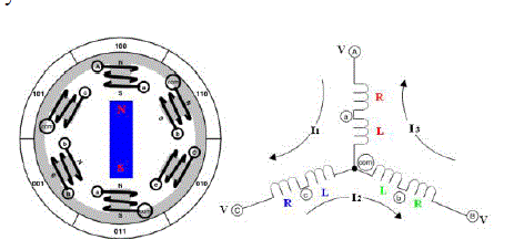 |
| The stator is excited by 3 phase AC supply and rotor is made up of permanent magnet. The transfer function of the BLDC motor which is taken in this paper is given by [8]. |
 |
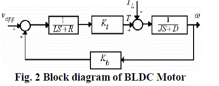
| The block diagram of the Bldc motor is shown in fig. 2 where L is inductance, R is resistance, Kt, Kb are torque and emf constants, J is moment of inertia and D is damping constant of the BLDC motor. |
 |
FUZZY PID CONTROLLER |
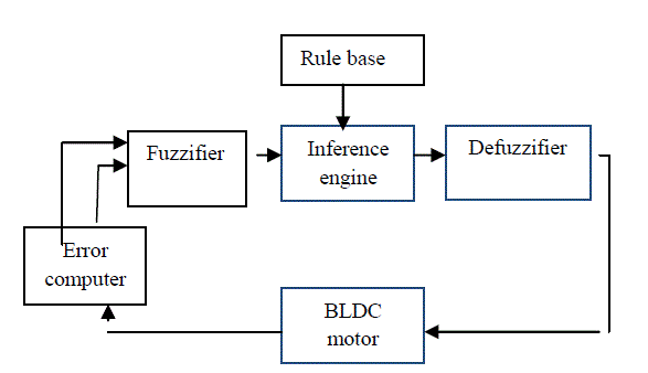
| Fig. 3 shows the basic structure of a fuzzy logic controller. It includes four major blocks: knowledge base, fuzzification, inference mechanism, and defuzzification. The knowledge base is composed of a data and a rule base. The data base, consisting of input and output membership functions. The rule base is made of a set of linguistic rules relating the fuzzy input variables into the desired fuzzy control actions. Fuzzy logic linguistic terms are most often expressed in the form of logical implications, such as If- Then rules. These rules define a range of values known as fuzzy membership functions. |
 |
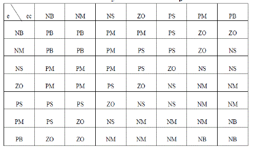
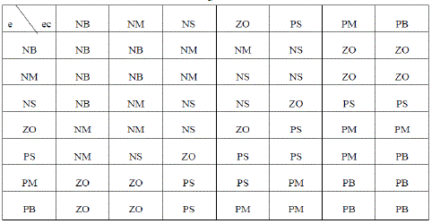
| The Fuzzy rules taken for ΔKp, ΔKi, ΔKd are as shown in table1, table2 and table 3 respectively. For all of the fuzzy designs, triangle membership functions (MFs) are used. The fuzzy reasoning results of outputs are gained by aggregation operation of fuzzy sets of inputs and designed fuzzy rules, where max-min aggregation method and Centroid defuzzification method are used. |
 |
 |
| The controller transfer function from the fuzzy PID is given by |
 |
GA BASED PID CONTROLLER |
| The basic principles of GA were first proposed by Holland. This technique was inspired by the mechanism of natural selection, a biological process in which stronger individual is likely to be the winners in a competing environment. GA uses a direct analogy of such natural evolution to do global optimization in order to solve highly complex problems [5].The GA architecture is shown in Fig. 4. |
| A basic genetic algorithm comprises three genetic operators. |
| selection |
| crossover, and |
| mutation |
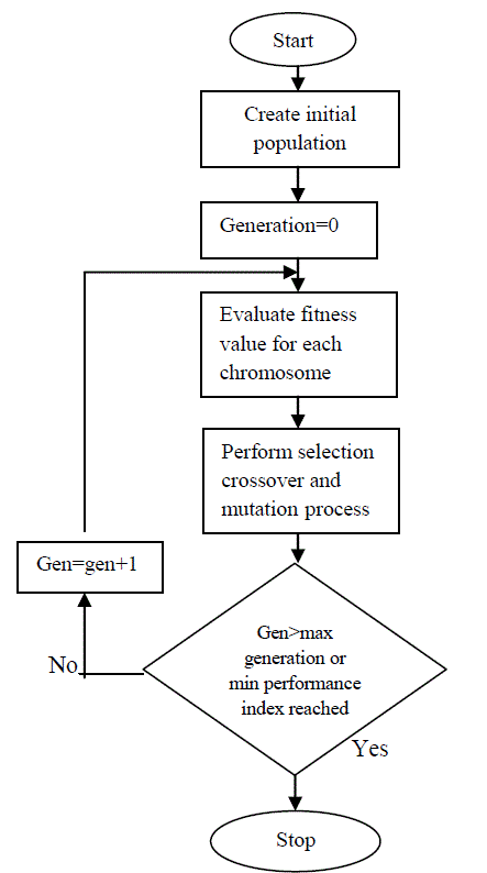 |
| `Starting from an initial population of strings (representing possible solutions), the GA uses these operators to calculate successive generations. First, pairs of individuals of the current population are selected to mate with each other to form the offspring, which then form the next generation. Selection is based on the survival-of-the-fittest strategy, but the key idea is to select the better individuals of the population, as in tournament selection, where the participants compete with each other to remain in the population. The most commonly used strategy to select pairs of individuals is the method of roulette-wheel selection, in which every string is assigned a slot in a simulated wheel sized in proportion to the string’s relative fitness. This ensures that highly fit strings have a greater probability to be selected to form the next generation through crossover and mutation. After selection of the pairs of parent strings, the crossover operator is applied to each of these pairs. The crossover operator involves the swapping of genetic material (bit-values) between the two parent strings. In single point crossover, a bit position along the two strings is selected at random and the two parent strings exchange their genetic material as illustrated below. |
| Parent A = a1 a2 a3 a4 | a5 a6 |
| Parent B = b1 b2 b3 b4 | b5 b6 |
| The swapping of genetic material between the two parents on either side of the selected crossover point, represented by “|”, produces the following offspring: |
| Offspring A’ = a1 a2 a3 a4 | b5 b6 |
| Offspring B’ = b1 b2 b3 b4 | a5 a6 |
| The two individuals (children) resulting from each crossover operation will now be subjected to the mutation operator in the final step to forming the new generation. The mutation operator alters one or more bit values at randomly selected locations in randomly selected strings. Mutation takes place with a certain probability, which, in accordance with its biological equivalent, typically occurs with a very low probability. The mutation operator enhances the ability of the GA to find a near optimal solution to a given problem by maintaining a sufficient level of genetic variety in the population, which is needed to make sure that the entire solution space is used in the search for the best solution. In a sense, it serves as an insurance policy; it helps prevent the loss of genetic material. |
| The controller transfer function from the GA based PID controller is given by |
 |
QFT CONTROLLER. |
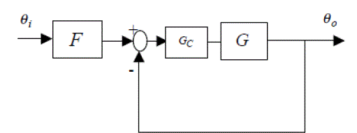
| QFT is a robust controller design technique for linear and nonlinear systems, with special emphasis on the use feedback for achieving good performance against uncertainty and disturbances. The control structure is illustrated in Fig. 5. The controller and pre-filter are designed by the QFT method; The QFT methodology makes use of Nichols charts, where on the horizontal axis the frequency is displayed, on the vertical axis the logarithm of the amplitude is displayed. |
 |
| The design procedure is summarized as follows: |
| A. Template Generation |
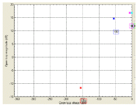
| Template is a region in the Nichols chart that represent the frequency response of the uncertain plant at a particularly frequency. Template generation is a key step in practical QFT design. Fig. 6 shows the generated templates for the BLDC motor and its frequencies. Design frequencies are chosen based on the designer’s experience, plant considerations and some trial and error. |
 |
| B. Closed Loop Performance Specification |
| In QFT, the design specifications should be given in the frequency domain. These specifications define bounds in the Nichols chart that should be satisfied by the nominal open loop transfer function. The control system also should attenuate the output disturbances. These specifications are defined as follows: |
| 1) Robust Stability: To ensure the robust stability of the closed loop system, the following constraint is applied on the peak magnitude of the closed loop frequency response [3] |
 |
| Where L is the open loop transfer function with uncertainly. ML is constant over the frequency and corresponds to the minimum phase margin (PM) and can be derived from the following equation [3]: |
| PM = 180ο _2cos-1(0.5/ML) |
| As mentioned before, the minimum phase margin that we should achieve is 60, ML=1.0 ML is chosen to be 1.2 for BLDC Motor. |
| 2) Robust Tracking: The following constraint is applied on the magnitude of the closed loop system for tracking the reference input [13] |
 |
| And, where F is the pre filter, G is the controller, P and is the plant with uncertainty.TR is the closed loop transfer function, TRL and TRU are lower and upper tracking bounds, which should be specified by the designer according to plant considerations. TRL and TRU are chosen to be 0.95 and 1.05 respectively. These constants are systematically derived from the desired step response of the system with a rise time of 0.05ms, a settling time of less than 0.1 ms, an overshoot of less than 0.5% and a steady state error of less than 0.1% in step response. |
| 3) Robust Control Effort: A constraint bound for signal control is considered as follows: |
 |
| where ∂u =0.02 due to a physical constraint |
| C. Loop Shaping: The key step in the QFT controller design is shaping the nominal open loop transfer function to satisfy the composite bound at selected frequencies. After some trial and error, we have achieved an appropriate design. The QFT control is used to achieve reliability and robustness, where QFT deals with robust stability margins and robust performance specifications (disturbance rejection, reference tracking, etc). The QFT methodology converts closed-loop system specifications and model plant uncertainty in a set of constraints or bounds for every frequency of interest that will have to be fulfilled by the nominal open loop transfer function. They are represented on a Nichols chart. Such a great integration of information in a set of simple curves will allow designing the controller using only a single plant, which is the nominal plant. |
| In the design stage (loop-shaping), the controller Gc(s) is synthesized by adding poles and zeros until the nominal loop, defined as LO = GOGC , lies near its bounds. An optimal controller will be obtained if it meets its bounds and it has the minimum high frequency gain. The general formulation for the controller structure is expressed by the following transfer function: |
 |
 |
| Once the controller has been designed, the pre-filter should be planned to put the magnitude variation of the closed loop transfer function in the desired regions which is specified by the tracking specifications and this is the final step of the QFT design procedure. |
RESULTS |
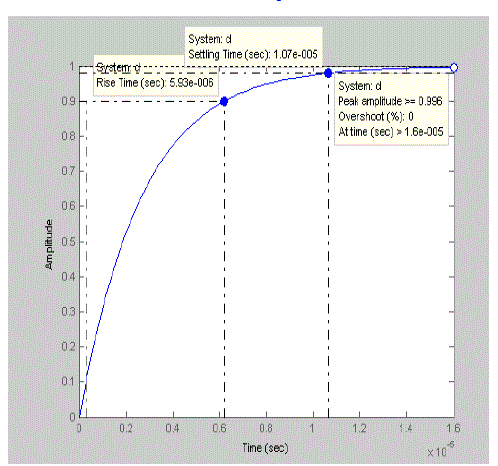
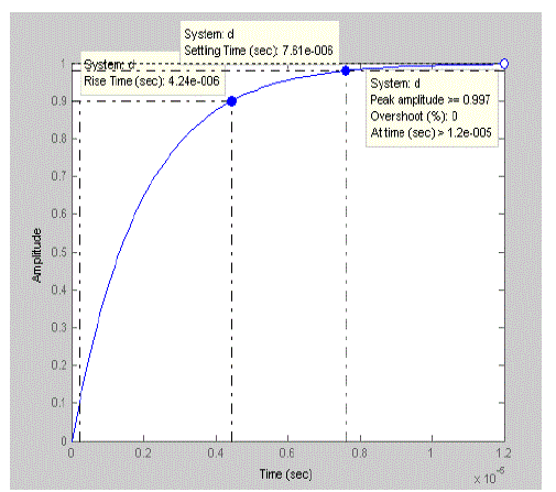
| The time response characteristics obtained from the design of various controllers are shown in the figures below. The rise time, settling time and peak response from the three controllers are tabulated in table 4. The results show that the QFT controller has got better performance characteristics when compared to other types of controllers. The results illustrate the robust stability and system disturbance rejection. |
 |
 |
CONCLUSION |
| The paper presents a robust controller design with the QFT technique, fuzzy logic and GA for a BLDC motor. The robust stability and transient performance requirements are satisfied when applying the QFT controller in the presence of system parameters uncertainty. The major difference between the QFT controller design versus other known robust techniques is that the closed-loop system performance is designated and supervised in every step of the QFT design. The QFT design technique offers transparency of the controller design over robustness and dynamic requirements, where the controller structure is composed of several elements known from the classical control theory, like: lead-lag, lag-lead compensators, integral action and other. Also, it was clear that the obtained controller was simple, robust and of a low order. The main focus of the future research on the QFT controller design will be system energy optimization. |
References |
|