ISSN ONLINE(2319-8753)PRINT(2347-6710)
ISSN ONLINE(2319-8753)PRINT(2347-6710)
Bhagyashri B. Kale, J. K. Singh
|
| Related article at Pubmed, Scholar Google |
Visit for more related articles at International Journal of Innovative Research in Science, Engineering and Technology
This paper deals with design and comparative analysis of square array of square Parasitic Patches (PPs) and circular array of square PPs on superstrate layer fed by Microstrip Antenna (MSA) on the basis of gain, bandwidth, efficiency and number of PPs required to obtain desired performance. The first structure consists of MSA, which feeds square array of 5×5 square PPs printed below a FR4 superstrate and positioned at about 0.5λ0 height from the ground plane. While other structure consists of a MSA, which feeds circular array of 18 square PPs printed below a FR4 superstrate and positioned at about 0.5λ0 height from the ground plane. It is shown that the circular arrangement of square PPs have better performance. The analysis is useful in selecting the antenna structures for particular application which require higher performance with lesser antenna size. Antenna structures are attractive solution for several wireless communication systems, such as base station cellular systems, satellite systems, and point-to-point links.
Keywords |
| High gain wideband antenna, directive antenna, multilayer, stacked antenna, ISM, Fabry-Perot Cavity. |
INTRODUCTION |
| MSA is one of the most usable antennas at frequencies greater than 1GHz. MSA has many advantages like low profile, low cost, easy to fabricate, easy to feed etc. Beside all these advantages MSA suffers from disadvantages like low gain, low bandwidth, low efficiency etc. [1]. |
| High gain antennas are traditionally realized by line fed antenna arrays but a high gain antenna having single-feed system is always desirable as it offers low complexity compared to feeding networks used in conventional antenna arrays. Reflectarray antennas have been proposed [2-4]. Reflectarray avoids the feed-line network and can be made flat or conformal but suffers from low efficiency due to dielectric losses. Gain enhancement techniques based on Fabry-Perot cavity (FPC) where a partially reflecting surface (PRS) formed by a dielectric layer or a periodic screen at approximately 0.5λ above a ground plane is used. The gain of PRS antenna depends on the reflection coefficient of PRS and radiation characteristic of feed antenna [5-8]. |
| High gain antennas with artificial magnetic conductors based on FPC model have been proposed [9]. High gain antennas using a frequency selective surface, electromagnetic band gap resonator [10-11]. High gain antennas using PPs on a superstrate have been reported. These antennas offer high efficiency, low side lobe level and avoid feed network, but have narrow bandwidth [12-13]. The techniques for improving the gain and bandwidth by arranging parasitic elements above the feeding MSA are investigated [14-17]. A high gain and wideband FPC antenna with circular array of square PPs on a superstrate layer have been proposed [18]. |
| Here antenna structures for high gain and wide bandwidth applications are designed using an array of PPs at about 0.5λ0 height in square and circular manner. The comparative analysis is carried out and presented in this paper. The first antenna structure consists of MSA, which feeds square array of 5×5 square PPs printed below a FR4 superstrate and positioned at about 0.5λ0 height from the ground plane. While other antenna structure consists of a MSA, which feeds circular array of 18 square PPs printed on a FR4 superstrate and positioned at 0.5λ0 from the ground plane. The antenna structures are designed to operate over 5.15-5.875 GHz band, which covers 5.15-5.25 GHz, 5.25-5.35 GHz and 5.725-5.875 GHz ISM bands. Structures are easy to fabricate as the feed-line network is completely avoided. Gain as well as bandwidth is improved by resonating the MSA, PPs and FPC at different frequencies. The different element of a structure resonating at different close by frequencies results in gain and bandwidth improvement. The antenna design and optimization is carried out using commercial IE3D software [19]. The following sections deal with the antenna geometry, design theory, simulation results. Radiation pattern and impedance variation of antenna structures are also described. |
II. ANTENNA DESIGN METHODOLOGY AND GEOMETRY |
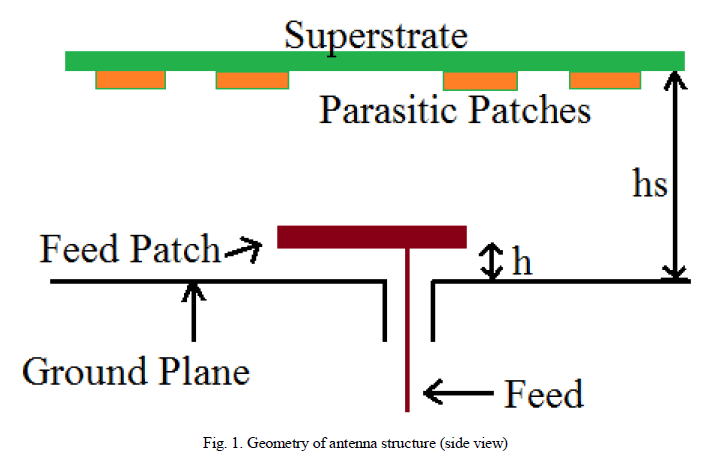
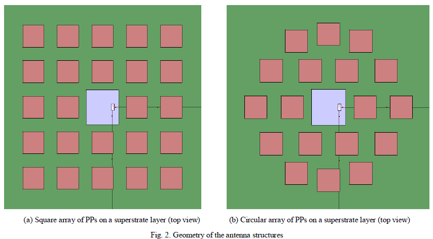
| In this section, antenna design methodology and Geometry is described. The side view of the square array of 5×5 square PPs below superstrate layer antenna structure is shown in Fig. 1. The Feed Patch (FP) is a metallic patch of 0.5 mm thickness. It is placed at a height h = 3mm from the ground plane. The PPs are fabricated at bottom side of FR4 superstrate layer at about hs=0.5λ0 height, where λ0 is the free space wavelength corresponding to central frequency 5.5 GHz. Relative permittivity and loss tangent of FR4 superstrate is 4.4 and 0.02 respectively. For the purpose of high efficiency, air is used between FP and ground plane, superstrate layer and FP as a dielectric medium. A 50 Ω coaxial probe is used to feed the FP. The antenna is designed to operate over 5.15-5.875 GHz frequency band. Geometry of square array of PPs is shown in Fig. 2(a), while geometry of circular array of square PPs (top view) is shown in Fig. 2(b).The side view of antenna structure with circular array of square PPs is same as shown in Fig. 1. |
 |
 |
| The structure can be considered as a cavity resonator with FSS or superstrate. The structure is an extension of a half wavelength FPC consisting of a ground plane and a partially reflecting surface which results in multiple reflections between superstrate and ground plane. A broadside directive radiation pattern results if the distance between the ground plane and superstrate is such that it causes the waves emanating from superstrate to be in phase in normal direction. |
| If reflection coefficient of the superstrate is ρejψ and f(α) is the normalized field pattern of feed antenna, then normalized electric field E and power S at an angle α to the normal is derived in [5] |
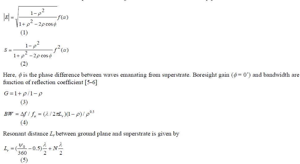 |
| Here 0 ïÃÂù is expressed in degree and N=0, 1, 2, 3 etc. |
| When a MSA feeds circular array of square PPs on a superstrate layer, high gain broadside radiation can be achieved if the PPs are fed in phase and current induced at patches are in phase. Since the PPs are positioned at different location and at different distance from FP, therefore, feed to each element involves amplitude tapering and phase delay. Beside the amplitude tapering due to distance, there is additional amplitude tapering due to the radiation pattern of MSA. The amplitude tapering results in decrease in gain but it improves bandwidth and side lobe level. There is little phase delay in feed to different PPs, which leads to bandwidth improvement. Hence, high gain wide band array antenna with a desired SLL can be achieved. |
| Gain and bandwidth of such structure depends on the reflection coefficient of superstrate. The gain increases but the band width decreases with reflection coefficient of superstrate. Therefore, PPs on a dielectric layer are fabricated to enhance the reflection coefficient and the gain. As the waves emanating from the superstrate must be cophasal, the gain of the antenna depends on the spacing between patches and their dimensions. Identical size of PPs leads to different close resonant frequencies resulting into wide bandwidth. |
III. COMPARATIVE ANALYSIS ON INFINITE GROUND PLANE |
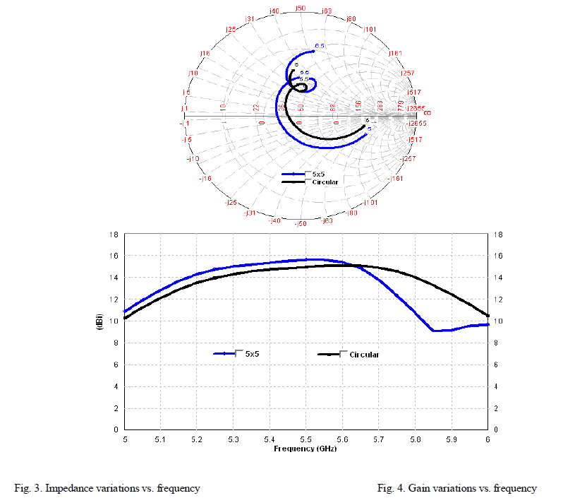
| MSA using a metallic patch of 0.5 mm thickness at a height h = 2 mm from the infinite ground plane is designed and then a superstrate layer of FR4 at about hs = 0.5λ0 height is placed. The structures are optimized to operate over 5.15- 5.875 GHz. MSA provides a gain of 8.5 dBi which increases to 11.45 dBi when FR4 superstrate of 1.59 mm thickness is placed above MSA. Placing superstrate above MSA results into increase in capacitive impedance. To compensate it, h is increased to 3 mm and hs is optimized to 30.9 mm, which is slightly more than 0.5λ0. As a result, impedance bandwidth is improved and VSWR less than 2 is obtained over 5.15-5.875 GHz. Then square array of 5×5 PPs is placed below FR4 superstrate. The square PP array antenna structure offers 13.8% impedance bandwidth determined from smith chart and maximum gain of 15.7 dBi with 3 dB gain bandwidth of 10%. |
| Similarly, for second structure, inner circular array of square PP array consisting of 6 PPs is placed above MSA. Optimized structure provides VSWR less than 2 over 5.15-5.875 GHz and 12.5 dBi gain. Outer circular array of 12 element square PPs is placed on the superstrate layer and the structure is optimized. The structure provides gain of 15 dBi with 3 dB gain bandwidth of 14.3% and impedance bandwidth of 13.8%, which covers 5.15-5.25 GHz, 5.25-5.35 GHz and 5.725-5.875 GHz ISM bands. The optimum dimensions are h=3 mm, hs=30.9 mm, whereas square PPs is of 16 mm × 16 mm each. Distance between PPs is optimized to obtain desired gain bandwidth performance. |
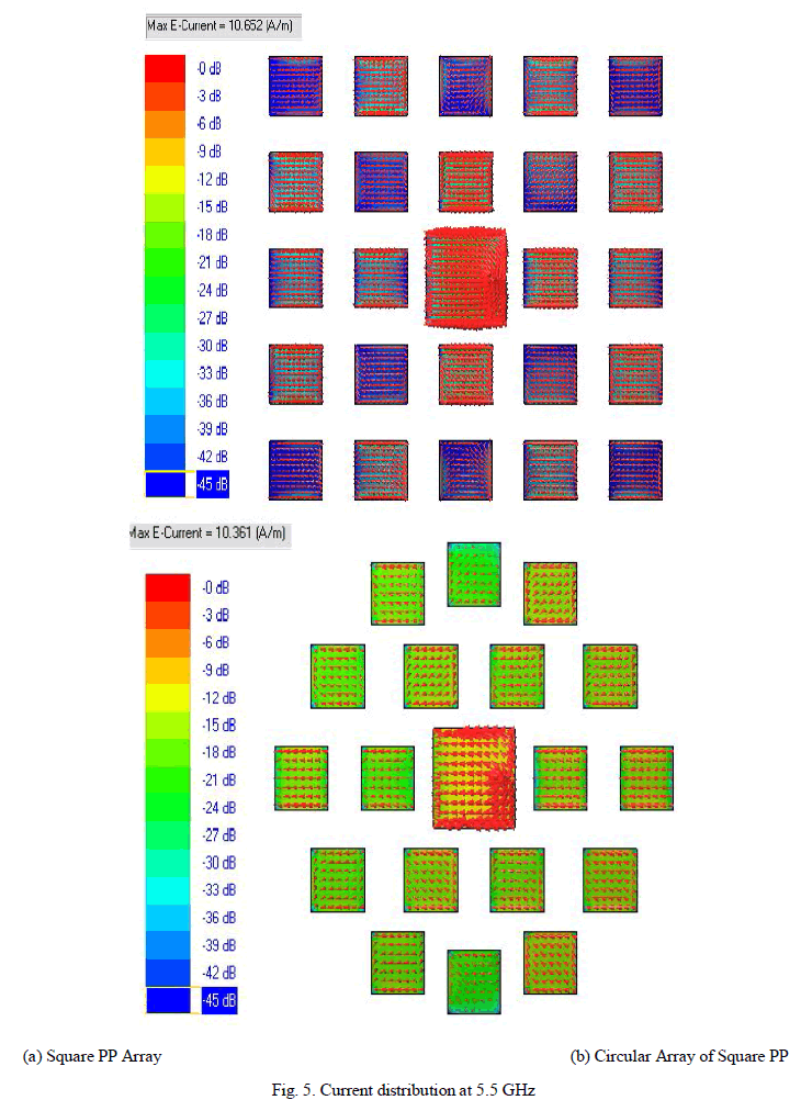
| Comparison of two structures with respect to gain, bandwidths and number of PPs on infinite ground plane is tabulated in table I. Impedance variation of structures is shown in Fig. 3. Whereas, gain variation for both structures is shown in Fig. 4. Vector current distribution at the feed and PPs at 5.5 GHz for both structures is shown in Fig. 5. The current distribution shows that the amplitude of current induced in PPs decrease as its distance from feed element increases. The superstrate affects the phase and amplitude distribution of fields. The phase distributions of the fields with a superstrate are observed to be more uniform than one without the superstrate. The superstrate has a focusing or phase smoothening effect and thus increases the effective aperture area, resulting in gain improvement [7-8]. Also it is observed that the current in circular array is more uniform than that of square array of PPs, which contribute more in gain as well as bandwidth improvement. |
 |
 |
 |
IV. DESIGN AND COMPARISON ON FINITE GROUND |
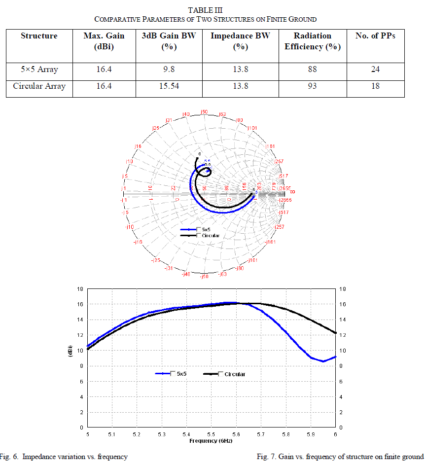
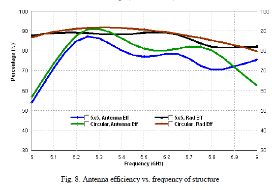
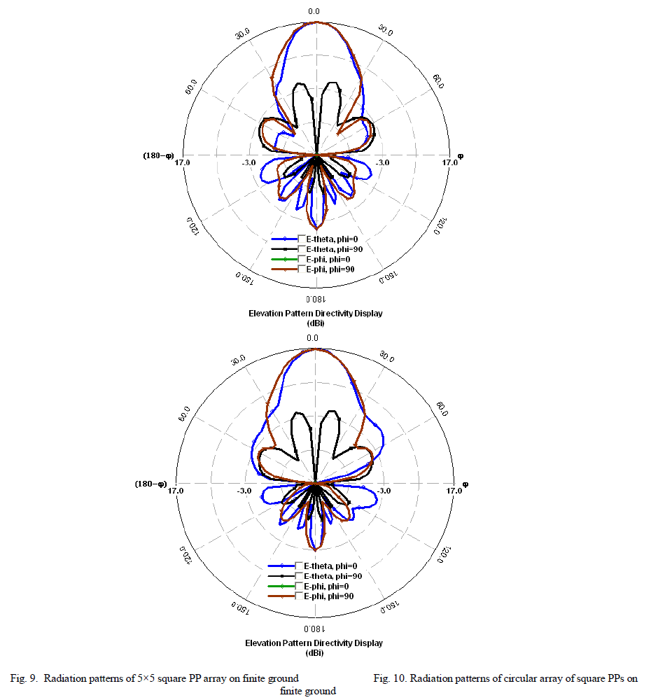
| The antenna structures of 5×5 square PP array and circular array of square PPs with 18 elements are designed on square finite ground plane of size 3λ0×3λ0. The square PP array antenna structure offers 13.8% impedance bandwidth determined from smith chart and maximum gain of 16.4 dBi with 3 dB gain bandwidth of 9.8%. Whereas circular array square PPs provides same impedance bandwidth and maximum gain. However, 3 dB gain bandwidth is 14.54% which is more as compared to square array of PPs. Gain bandwidth increases due to uniform feeding received by circular arrangement of PPs from the FP. It is observed that the gain increases slightly with the finite ground plane. It is due to constructive interference between radiated and reflected waves at particular dimensions of finite ground. Comparison of two structures with respect to gain, bandwidths, efficiency and number of PPs on finite ground plane is tabulated in table II. The impedance variation is shown in Fig. 6. Gain variation is shown in Fig. 7. The radiation efficiency of square array is about 90% and circular array provides efficiency more than 90% radiation efficiency as shown in Fig. 8. Radiation patterns of 5×5 square PP array and circular array of square PPs on finite ground at 5.5 GHz are shown in Fig. 9 and Fig. 10 respectively. Radiation patterns are symmetrical in broadside direction. SLL is less than -20 dB and F/B is about 18 dB in Square PP array and about 20 dB in circular array of square PPs with cross polarization less than -18 dB which is appreciable for high gain wideband antennas. |
 |
 |
 |
V. CONCLUSION |
| In this paper, design and comparative analysis of square array of square PPs and a circular array of square PPs on superstrate layer fed by MSA is carried out. It is observed that, the circular arrangement of square PPs have better performance in terms of gain bandwidth, efficiency and number of PPs. Number of PPs in circular array is less than that of square array of square PPs to obtain similar performance. This is due to uniform feeding from FP to PPs in circular arrangement as shown in current distribution. The size of circular array antenna is less as compared to square array antenna. The analysis is useful in selecting the antenna structures for particular application which require higher performance with lesser antenna size. The analyzed antenna structures are suitable for satellite as well as terrestrial communications. |
References |
|