International Journal of Innovative Research in Science, Engineering and Technology
ISSN ONLINE(2319-8753)PRINT(2347-6710)
ISSN ONLINE(2319-8753)PRINT(2347-6710)
Sameer More 1, Pravin Medankar 2, Prof.Mahesh Nagargoje 3
|
| Related article at Pubmed, Scholar Google |
Visit for more related articles at International Journal of Innovative Research in Science, Engineering and Technology
Vibrations are occurred due to the slight twist in the crankshaft during the power stroke. The periodic combustion cycles of a 4-stroke engine produce torque fluctuations which excite torsional vibration to be passed down the drive train. The resulting noise and vibration, such as gear rattle, body boom and load change vibration, result in poor noise behavior and driving comfort.The objective while developing this concept was to isolate the drive train from the torsional vibrations.This paper includes the development of inertia augmentation mechanism and development of optimized flywheel using this mechanism. The dual mass flywheel comprises primary flywheel and secondary flywheel and two springs.
Keywords |
| Dual mass flywheel, Torsional vibration, Inertia augmentation mechanism, Driving comfort, Damping |
INTRODUCTION |
| Function of engine flywheel is to even out the fluctuations in power and thereby make a smooth transmission of power to wheels. All engines have flywheels or weighted crankshafts that balance out compression and power strokes, maintain idle, aid starting and reduce component wear. If the flywheel is too light the motorcycle requires more effort to start, idles badly, and is prone to stalling. Weight is not the important factor here, but inertia. Inertia is stored energy, and is not directly proportional to flywheel weight. ItâÃâ¬ÃŸs possible to have a light flywheel with much more inertia than a heavier flywheel. In any event, except for when the clutch is slipped all flywheel weight reduces acceleration. There is no engine speed or other condition where extra flywheel weight helps. Obviously, thereâÃâ¬ÃŸs a certain minimum amount of flywheel inertia that should be present for several reasons such as idle stability, tolerance of high compression, cam overlap, better clutch operation for low speed and traffic operation, fewer load reversals on the driveline during low speed, better traction, etc. |
| Thus it is safe to interpret from above discussion that the flywheel inertia plays a major role in vehicle optimized performance and by suitable modifying the mass of flywheel can be reduces by still maintaining the inertia. The arrangement of the dual mass flywheel is a suitable answer to the above problem statement where in the inertia is increased using two set of masses phased opposite to each other. In our approach we shall focus on development of new flywheel system using a spring mass system of useful vibration to improve inertia of flywheel there by achieve higher efficiency using lower mass, lower size flywheel. |
LITERATUREREVIEW |
| Generally various studies have been made on flywheels. According to it the periodic combustion cycles of a 4-stroke engine produce torque fluctuations which excite torsional vibration to be passed down the drive train. The resulting noise and vibration, such as gear rattle, body boom and load change vibration, result in poor noise behavior and driving comfort. |
| The basic concept for this paper is taken from United States Patent Document of Lee et al. The main concept of work is begun by studying problems with conventional flywheel. Torque estimation of dual mass flywheel is explained by Ulf Schaper et al which has been useful for this paper. Effect of dual mass flywheel in case of noise in vehicular powertrain system has been discussed by S Theodossiades et al. According to their research dual mass flywheel has good impact on noise reduction as compare to conventional flywheel. |
III. PROPOSED METHODOLOGY |
| The arrangement of the dual mass flywheel is best explained by the mathematical model below. The model is a two spring two mass model graphically represented as below |
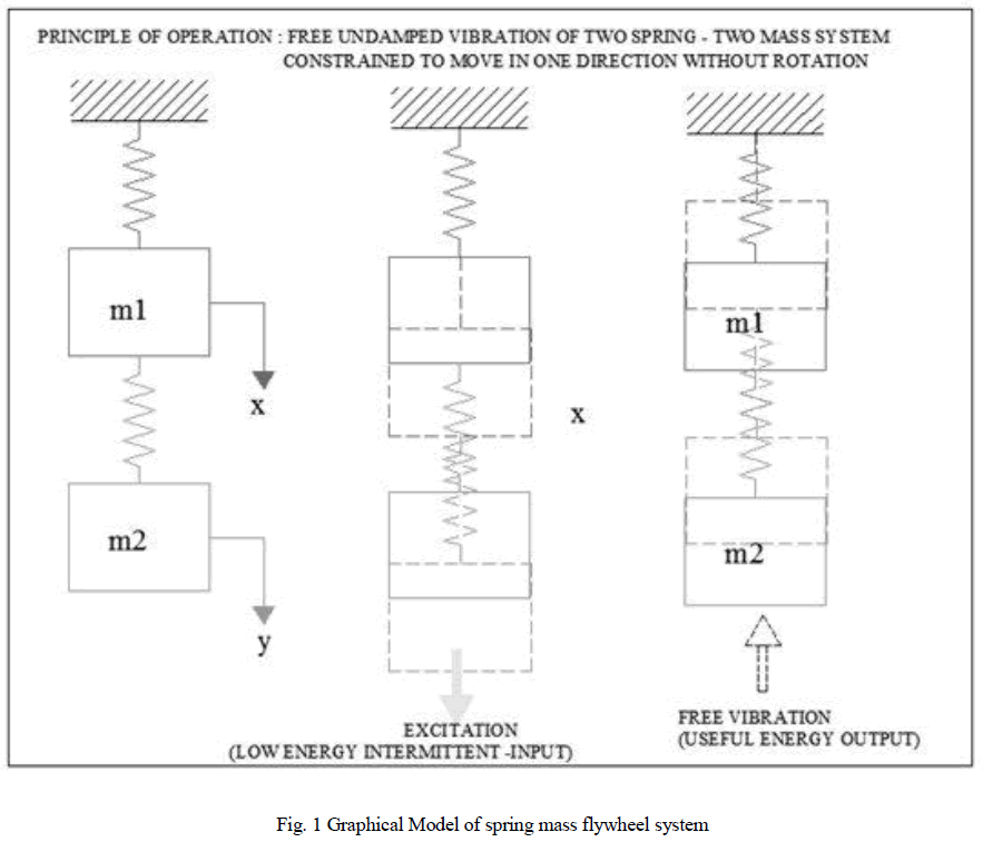 |
| The figure shows free un-damped vibrations set up of two mass- two spring system. As shown in the figure the input to the system is in the form of an low energy intermittent input from any power source (excitation) , this results in free undamped vibrations are set up in the system resulting in the free to and fro motion of the mass (m1)& (m2) , this motion is assisted by gravity and will continue until resonance occurs, i.e., the systems will continue to work long after the input (which is intermittent) has ceased……Hence the term free energy is used. |
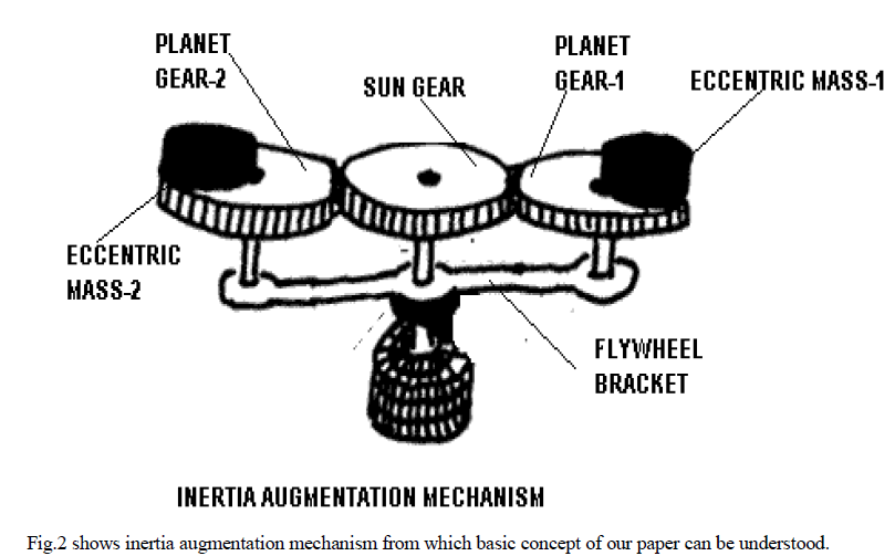 |
| Fig.2 shows the inertia augmentation mechanism in which it can be seen that two eccentric masses are placed on planet gears 1 and 2which are mounted on flywheel bracket. Fig. 3 simplifies the concept of inertia augmentation mechanism. |
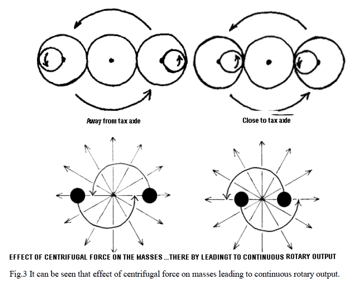 |
| From fig. 3 we can conclude that using two such masses instead of a single rigid mass may be helpful for continuous rotary motion in case of flywheel. Therefore flywheel will be divided into two masses i.e., primary and secondary masses which will be connected by lubricated spring sets. It effectively isolates torsional vibrations. |
| Dual mass flywheel is represented in figure below: |
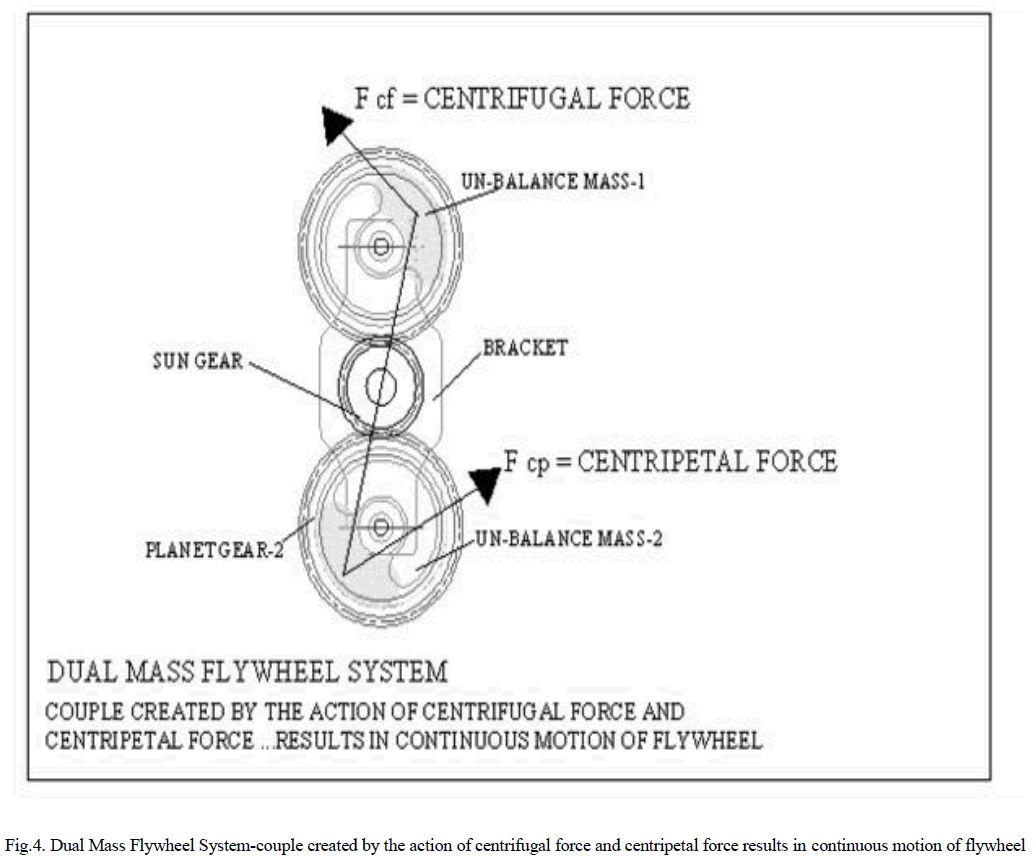 |
| From Fig.4 it is clear that in addition to the mass of the flywheel , the couple owing to the centrifugal and centripetal forces keeps the flywheel into motion for longer time …thereby increasing the work done by the system…hence the output from the given system increases. |
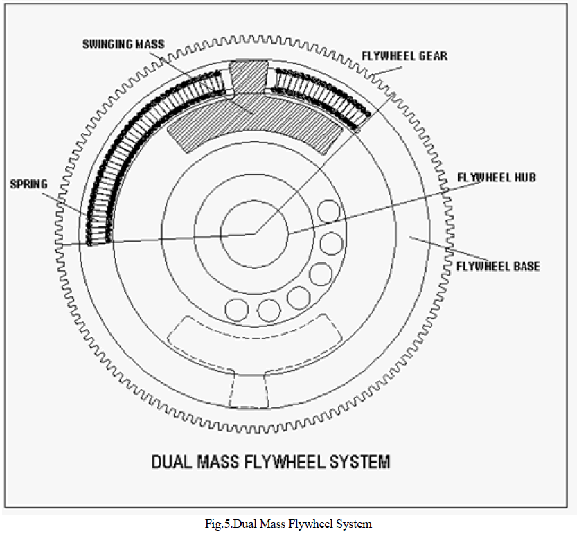 |
| The dual mass flywheel system is as shown above. The flywheel comprises of the flywheel hub which is keyed to the engine shaft,. Hub carries the flywheel body, on which the flywheel gear ring is mounted. The flywheel body is recessed at the rim inner side to receive the spring. Two springs and two masses are used hence the flywheel has dual masses …from which the name of the flywheel originates. |
| As the engine power is delivered to the flywheel, the jerk applied will set the flywheel into motion, so also the jerk is applied to the masses, and as explained in the two spring two mass system the two masses oscillate to generate the „free energyâÃâ¬ÃŸ as explained earlier. The motion of the masses gives extra impetus to the flywheel body due to which we get extra revolutions from the same jerk as applied to the conventional flywheel. Thus it is able to achieve more inertia with same mass of flywheel with the dual mass flywheel arrangement. |
IV. RESULT |
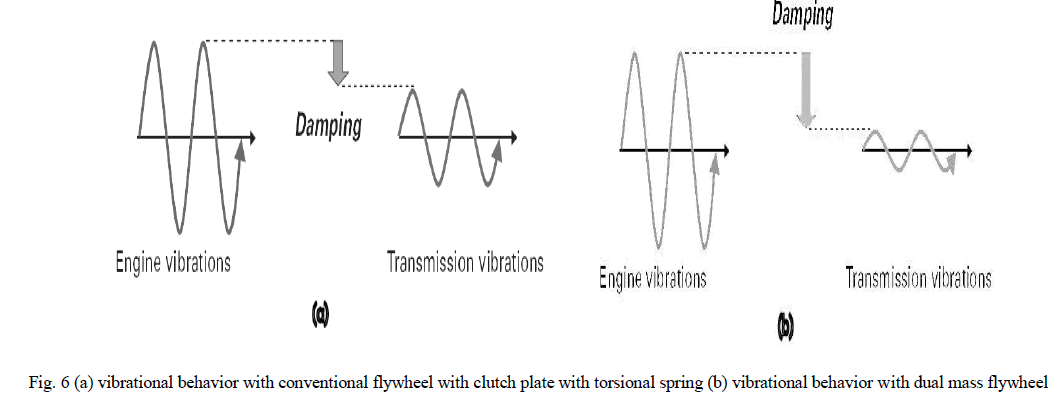 |
| With a conventional flywheel, the torsional vibrations in the idling range are transferred practically unfiltered to the gearbox and cause the gear teeth edges to knock together (gearbox rattle). |
| The complete isolation from torsional vibration can be obtained as shown in fig. 6.The spring/damper system of the DMF filters out torsional vibration caused by the engine. This prevents gearbox components knocking against each other – rattling does not occur and the drivers demands for higher comfort can be fully met. |
V. CONCLUSION |
| In this way, finally we conclude that power output of engine is increased by implementing the dual mass flywheel system. We also come to know that torsional vibrations are reduced. Hence preventing gear box components knocking. Moreover the fuel consumption can also be reduced. Also the power output increases. Result also shows that the dual mass flywheel System is more efficient than the conventional flywheel System. |
References |
|