ISSN ONLINE(2319-8753)PRINT(2347-6710)
ISSN ONLINE(2319-8753)PRINT(2347-6710)
| Vigneshwar Palanisamy, Venish Joe, Yuvarai.S Final Year - B.E. - Mechanical Engineering, Hindusthan College of Engineerning & Technology, Coimbatore, Tamilnadu, India. |
| Related article at Pubmed, Scholar Google |
Visit for more related articles at International Journal of Innovative Research in Science, Engineering and Technology
With the advancements in Engineering, we have been witnessing some drastic leaps and slopes on every edge of the possibilities and been making efforts to get the best out of everything. Various ideas have been brought out to seek the most efficient outcomes in all the sectors. Among those, IC Engines have been one of the greatest inventions by humankind. Many developments are made in them and one such thing is the Opposite piston engines. They have many architectural advantages like good balancing, high thermal efficiency, less fuel consumption, high power density, torque etc., this type of engine ceases itsexistence today mainly because its emission issues and its complexity. We used the concept of this opposite piston engine to develop a novel cross cylinder four piston synchronous engine which will be more efficient than the conventional engine. This engine will have all four pistons acting simultaneously producing four power strokes at the same time to achieve maximum torque with less balancing issues. Also our concept is to provide inlet and exhaust ports on either side of the cylinder. This allows the reduction of port opening and closing time and thus improvising, making it suitable for any kind of cylinder configuration for their efficient usage. Various parameters of this engine such as torque, rpm, efficiency etc., is validated through the fabricated model, manual calculation and by simulation.
Keywords |
| Opposite piston engine, Transient-structural analysis, Macdizzy cylinder mapping, balancing of IC engines. |
INTRODUCTION |
| Energy can be neither created nor destroyed but can transformed from one form to other form of energy. This is principle behind everything in this universe. Internal combustion engine is no exception to it. Over the years various researches have been done in the field of internal combustion engine to optimize its performance. In this paper we have developed a concept to maximize the thermal efficiency of internal combustion engine. |
| Objectives |
| To design an engine that utilizes the maximum thermal energy available and thereby increasing the performance of that engine than the already existing internal combustion engines. |
| Concept |
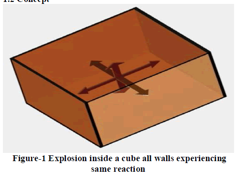 |
| Assume an explosion is happening inside a cube, waves will propagate in all direction thus all the walls of the cube experiences same force. Now we are fixing five sides of the cube and allowing only side of the cube to move free. Comparing this, the same is happening in IC engine. Inside a closed chamber an explosion takes place and a portion of area of the chamber is allowed to move. (i.e. piston area) |
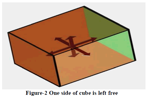 |
| In the above cube example, all the sides are experiencing same force so now we are allowing two faces to move. Also assume the movement of side is used to do work. Thus the area exposed to do useful work increases twice as in the previous case. Hence more work will be done in this case. Comparing the same with IC engine if we exposed more area to do useful work, ultimately thermal efficiency of that engine increases. This is done in opposed piston engine where two piston (twice the area) are exposed to the combustion. It is one of the reason that opposed piston engine have more thermal efficiency than the conventional IC engine. Other reason for high thermal efficiency is that these engines do not have cylinder head, thus less loss of heat. Opposedpiston engines, when properly sized and configured, have inherent thermodynamic advantages. |
DESIGN |
| To implement this concept we decided to design a four cylinder opposite piston engine. For ease of fabrication we decided that we go with two-stroke engine. Assuming that the engine has 2000 CC four cylinder engine we designed the engine using Solidworks and Pro-E software. |
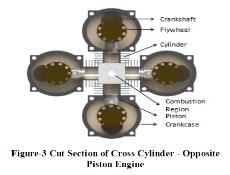 |
| This opposite piston engine will have all the component of the conventional internal combustion engine expect the cylinder head. And the major difference is that pistons are placed opposite to each other and the single engine may have four or two output depending where it is four or two cylinder engine. But we have to maintain the proper timing of piston which is essential feature of every engine to get proper combustion. Hence it becomes essential to connect all pistons together so that we get a synchronous motion of pistons. |
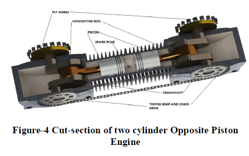
| All the cylinders are connected by the central block which acts as the cylinder head. It is an extension of cylinders not merely cylinder head and it contains the spark plugs. Since we deal with four cylinder engine it will be difficult to fabricate and test it, So we decided we will first design, fabricate and test a two cylinder opposite piston engine first and then four cylinder opposite piston engine. Also it will easy to explain the two cylinder opposite piston engine first and then four cylinder opposite piston engine. |
 |
WORKING |
| Two cylinder opposite piston engine working is explained first. Working is almost similar to the twostroke engine. |
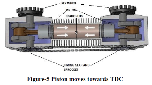
| As Pistons Moves towards TDC |
| When the pistons moves from BDC to TDC, both inlet ports at opposite sides of the cylinder opens and fuel mixture enters into the crankcase of the two stroke cylinder while at the same time, the precompressed fuel mixture enters into the cylinders where the fuel mixture is fully compressed as both the piston moves towards the center of the cylinder at TDC position. |
 |
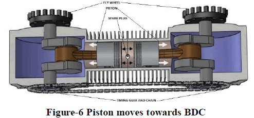
| 3.2 As Pistons Moves towards BDC |
| Now the spark plug produces spark and ignites the fuel to produce the power stroke. The combustion takes place at the center of the cylinder and the power is transmitted to the respective crankshafts equally. As the piston moves down towards the bottom dead center as the result of power stroke, burnt gases are evacuated through the two exhaust ports. At the same time fuel from the transfer ports comes into the combustion chamber and the cycle continues. Both the crankshafts are connected by the chain and sprockets to maintain the similar positions (i.e.., BDC and TDC) of both pistons towards the center (synchronous movement of pistons). |
 |
| Working of four cylinder opposite piston engine: |
| The working of four cylinder opposite piston engine is almost similar to the working of two cylinder opposite piston engine expect that four pistons facing each other and all these pistons are connected by gears to have exact synchronous movement of pistons. |
DOUBLE SIDE INLET AND EXHAUST PORT |
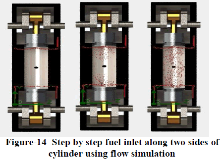
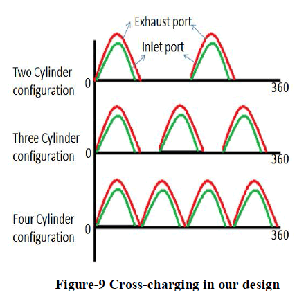
| Since we are using multi-cylinder configuration we have taken into account of cross-charging. After analyzing the Cross-charging in a 2-stroke Engine it is obvious that we have to reduce the port timing to make that engine suitable for four cylinder configuration. With the single side inlet and exhaust port configuration it difficult to reduce the port size beyond a certain limit. So what we decided to provide inlet and exhaust port on both side of the cylinder. With this configuration fuel will enter along both side of the cylinder. Hence the mass flow rate increases. Here the requirement is not to increase the flow rate but to decrease the port timing. To do that, we decreased the reduced the port height. We can do this because of the two side inlets, there will be an increase in fuel flow twice the amount of fuel in the case of single side inlet. With this idea we designed our engine. |
 |
| Prediction of Port Size and Port Timing |
| For four cylinder configuration we need to have 90 degree as the exhaust port timing (opening and closing). This is very short time yet there are two inlets, this extra fuel inlet can be compensated for the short timing. We know the mass flow rate of fuel inlet according to the cylinder volume. Then assuming the engine with 2000 cc, four cylinders, Spark ignition running at 2200 rpm. We calculated the port area. Actually there will be four ports. Main transfer port, Front transfer port, Rear transfer port and Exhaust port. With the know cylinder volume, we predicted the mass flow rate, then calculated the following using the MacDizzy cylinder mapping procedure. |
| Crank radius = 60 mm |
| Stroke length = 120mm |
| Connecting rod length = 72 mm |
| L/D ratio = 0.9 |
| Where, L = length of the cylinder |
| D = diameter of the cylinder |
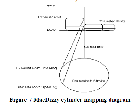 |
| We took a graph and drew a circle with radius equal to crank radius. Then from the top of the circle we marked a line at a point equal to length of the connecting rod which corresponds to the TDC of the cylinder. Then from the bottom of the circle we marked a line at a point equal to length of the connecting rod which corresponds to the BDC of the cylinder. As we want exhaust port to be opened for 90 degree, we want to mark 45 degree in the crank circle after BDC and 45 degree before BDC. It corresponds to that the exhaust port takes 45 degree for opening and 45 degree for closing. Then the same procedure is done for the inlet ports but set different angle. |
| Then from the 45 degree point on the crank circle we have to cut an arc of the length 72 mm (connecting rod length) inside the area of TDC and BDC in the graph. This corresponds to the height of the exhaust port. By the same procedure we determined the height of other ports. |
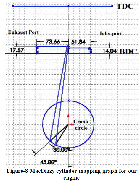 |
| With the cylinder volume fixed, the amount fuel inlet into each cylinder is constant. For providing the same fuel flow rate we have maintain the same port area. So the port area is fixed and we know the height of each port, for that we calculated the width of each port. Front transfer port (main port) - |
| Width: 51.84 mm. Height: 14.04 mm. |
| Exhaust port – |
| Width: 73.66 mm. Height: 17.57 mm. |
 |
ANALYSIS |
| To validate our idea we first designed a two cylinder opposite piston engine with the proportional dimension. We analyzed that design in ansys. Since we are using a new concept engine it is necessary to analyse all the parts associated with it. Also load in this engine will be varying with time. Thus we used transient structural analysis in ansys for determining the stress induced in various part of this engine. For example giving a pressure load on the piston we analysed the stress behaviour of the connecting rod. What is special about this analysis is that we can simulate the engine, at the same time we can view the load variation in the part we needed. Also we can determine the torque developed in the crankshaft by giving a pressure load on the piston. Likewise various analysis were done in ansys. |
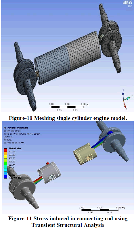 |
| Yet this results may not be an exact results, because this is a new concept we might not taken into account various other factor like chain loss, gear loss, mechanical loss etc. But our idea is to compare and validate. For example from analysis we get certain RPM and Torque. And with the fabricated model we get some RPM and Torque. When comparing the results we can predict what will be the output of the four cylinder opposite piston engine. |
FABRICATION |
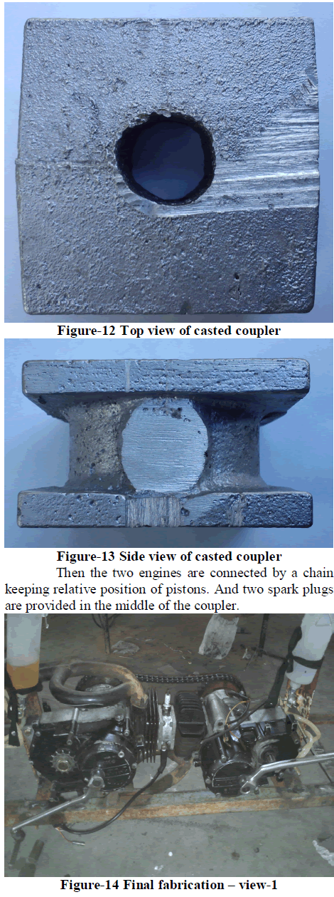
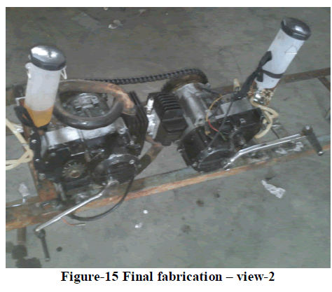
| As we already said for the easy of fabrication we decided to go with two-stroke opposite piston engine. We used two TVS-XL 70 CC engine for this fabrication. |
| Then we cast an aluminium central coupler that couples two engines together. |
 |
 |
CONCLUSION |
| The opposed-piston four cylinder engine will be a thermally efficient internal combustion engine, combining advantages surface area/volume ratio and high balancing. And with the double side inlet and exhaust concept these engine can be more efficient. Thus reengineering the opposed piston engine to make it suitable for the current emission standards with the recent advancement technology is the idea behind our project. Future idea is to make the same concept with a fourstroke engine with the help of electronic valve system, which will be the ultimate success of our concept and idea. |
References |
|