ISSN ONLINE(2319-8753)PRINT(2347-6710)
ISSN ONLINE(2319-8753)PRINT(2347-6710)
| Franco Antony, P J Albert, Rimin P R , Rino Disney,Sooraj M S , Sreevalsan S Menon Final year student, Department of Mechanical Engineering, Jyothi Engineering & College, Thrissur, India |
| Related article at Pubmed, Scholar Google |
Visit for more related articles at International Journal of Innovative Research in Science, Engineering and Technology
Many hybrid technologies are arriving which intend in reducing the fuel usagethere by increasing the fuel economy and also reduced exhaust emission. The majorhybrid now in market is being electrical. We build a pneumatic hybrid vehicle inwhich the vehicle is being powered up by an internal combustion engine and an airengine; output is being taken up as desired. The air hybrid engine absorbs a part of vehicle’s kinetic energy, stores it in an air tank in the form of compressed air, andreuses it to propel a vehicle during cruising and acceleration. Capturing, storing andreusing the energy to give additional power can therefore improve fuel economy,particularly in cities and urban areas where the traffic conditions involve many stopsand starts. Though some of the renewable energy sources like solar energy, bio fuelsare currently in practice, we are focused on pneumatic technology, since pneumaticapplications are wide all over the world, basic components and other equipment areeasily available and the fabrication is not so tough. Thus, the pollution and fuelconsumption of the internal combustion engine vehicles can be minimized by the useof the pneumatic hybrid vehicles.
Keywords |
| Pneumatic hybrid, Air hybrid, new hybrids, Zero pollution hybrid. |
INTRODUCTION |
| Fossil fuels (i.e., petroleum, diesel, natural gas and coal), which meet most of the world’s energy demand today, are being depleted rapidly. Also, their combustion products are causing global problems, such as the greenhouse effect, ozone layer depletion, acid rains and pollution, which are posing great danger for our environment, and eventually, for the total life on our planet. These factors are leading automobile manufacturers to develop cars propelled by alternative energies. Fuel consumption reduction has become the most important driver for engine, powertrain and vehicle development at present. The general concern about the effect of CO2 emissions on the environment and the global energy situation as well as the new taxes approved by government on CO2 emissions are forcing all car manufacturers to develop new technologies and to identify the best solutions for CO2 reduction. It is well known that for a relatively long time many research centres and the most innovative car manufacturers have been presenting to the market various “environment friendly” solutions that were promised to achieve better fuel economy. It can be said that quite a lot of the possible technologies have been in some way investigated or applied: at first within the internal combustion engine itself (downsizing and down-speeding, reduction of internal and auxiliary losses, various variable valve timing and lift systems etc.), and secondly (more promising) “around the engine”. From this second point of view, a hybrid approach has shown to be particularly promising. |
LITERATURE SURVEY |
| A compressed air vehicle is powered by an air engines, using compressed air, which is stored in a tank. Instead of mixing fuel with air and burning in the engine it to drive pistons with hot expanding gases; compressed air vehicles (CAV) use the expansion of compressed air to drive their pistons. The use of that air in the engine is 90 per cent efficient. The principle of the air engine is derived from the steam engine in which the pressure energy of steam is converted to kinetic energy. The air engine uses compressed air instead of steam. The compressed air has pressure which on expansion moves the piston (linear motion) which is converted to rotary motion through crank and connecting rod mechanism. In the compressed air engine, the cycle of operation gets completed with two strokes of the piston or one revolution of the crank. The two strokes are: |
| i. Expansion or Power stroke |
| ii. Exhaust stroke |
| 1 Expansion or Power stroke |
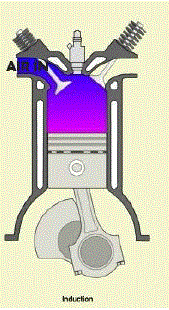
| During this stroke the piston moves from the TDC to BDC. At the beginning of this stroke the inlet valve is opened and allows the compressed air stored in the tank to expand inside the cylinder. This moves the piston down as pressure energy of air gets converted into kinetic energy thus producing a power stroke. Just before reaching BDC the specially designed cam mechanism closes the inlet valve and the piston uncovers an exhaust valve through which the expanded gas escapes to the atmosphere. This reduces the load on the piston by reducing the amount of air present inside the cylinder during return stroke. |
| The high pressure compressed air forces the piston towards the BDC. The inlet valve is opened for the purpose of entry of the compressed air. The exhaust valve remains closed. This stroke is responsible for power development and hence termed power stroke. Also expansion is the process undergone for which we can also term it as expansion stroke. The pressure decreases as the piston reaches BDC. |
 \ \ |
| 2 Exhaust stroke |
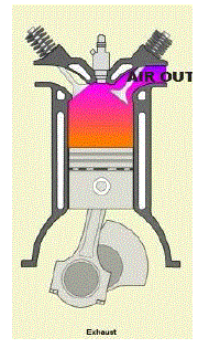
| During this stroke piston moves from BDC to TDC. Initially the piston covers the exhaust valve and the cam mechanism opens the exhaust valve. The remaining air trapped inside the cylinder is expelled to the atmosphere through the exhaust valve and the cycle continuous. At the end of expansion stroke the exhaust valve opens and inlet valve closes. The air inside the cylinder starts escaping through exhaust valve. The piston starts moving from BDC to TDC which also guides in expelling out the air. The exhaust valve closes when the piston reaches TDC. At the end of the exhaust stroke some air will be trapped inside the clearance volume. |
 |
PNEUMATIC HYBRID VEHICLE |
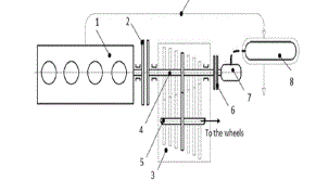
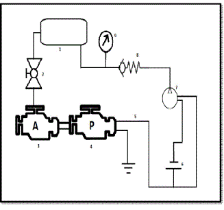
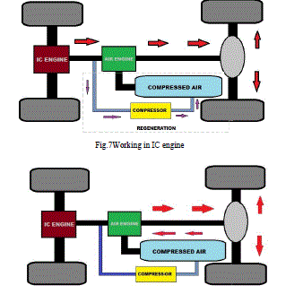
| One problem with traditional gasoline/electric hybrids is the high cost of batteries. Another is the increased complexity of needed two propulsion sources, adding to costs. What if you could get rid of the electric motor altogether, and store energy in something less expensive than batteries? That's the thinking behind the pneumatic hybrid system (fuel and compressed air). In our project we use limited range of compressed air energy storage technology by combining it with an internal combustion engine (ICE). Since air is used the term pneumatic has been introduced. In pneumatic hybrid engine we can take power from any of the sources (air or fuel). We had made a parallel hybrid vehicle model. Thus power can be taken from any desired source. |
 |
 |
FABRICATIN OF PHV |
| The various stages of fabrication process undergone are being explained below: |
| 1 Fabrication of Air Engine |
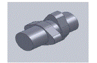
| For working of an air engine two stroke engine technologies is needed. But the market is now dominated with four stroke engines. So in our project we took a four stroke petrol engine and modified it in to a two stroke air engine. Our present engine camshaft rotates once for every two rotations of flywheel. For a two stroke it needs one rotation of camshaft for one rotation of the flywheel or for one rotation of flywheel there must be opening of both inlet and exhaust valves. |
| By altering the cam profile with double cam so that for one rotation of camshaft the inlet and exhaust valves will be opened twice. This is for the fact that in a four stroke engine for two flywheel rotation the camshaft rotates once. Thus four strokes are made so for two strokes with same arrangement the camshaft will have to open the inlet and exhaust valve twice. So we modify cam profile so that two lift is possible for both inlet and exhaust side. Thus for first quarter rotation of the camshaft we have power stroke, next quarter exhaust, third quarter again power stroke and fourth again exhaust. This design is adopted by us since no further modifications in timing gears and cylinder head is needed to accommodate the design. Thus only work to be done is reduced to cam profile. |
 |
| 2 Works on frame |
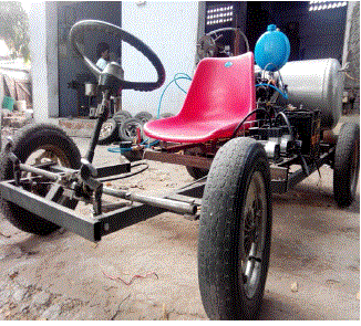
| After the work of making air engine the next work was on the frame making. The frame was made of MS tubes. The major works on frame was carried out with the MS 40*20*1.60 mm tubes. The corners and angles are being welded. The welding was made ensuring to carry maximum weight. The provisions were made in order to accommodate the tank, engines, battery, seat, steering etc. |
| 3 Works on wheel and wheel assembly |
| The next works were carried on wheels and its assembly. The rear wheels were assembled on the axle. The axle was made from steel rod of about 25mm diameter. The axle was mounted to the frame on rear side with help of plummer blocks. Thus two plummer blocks were used to hold the rear axle. One of the wheels is powered up while the other is free to rotate so as to allow differential action. |
| The front wheel has to be made suited for steering. So the assembly of front wheels is made in accordance. The front wheels are supported on a bearing so that the wheels can move in angular directions. For this a steering arm was made in accordance. Thus the two wheels are assembled to the knuckle of the steering arm. |
| 4 Works on steering and braking system |
| Steering as said earlier was made with rack and pinion arrangement. From the rack two tie rods are connected by welding to both sides and it was connected at ends to the steering arm. The steering assembly was placed above the frame by welding a MS tube along the frame and bolted to the same. Since the vehicle is designed with simplicity and without suspension the braking system was made simpler. An internal expanding type brake was provided to one of the front wheel. The vehicular speed has been reduced due to this. |
| 5 Assembly of air tank and engines |
| Now the air engine was positioned behind the frame allowing space further for the air tank. To place the tank a MS tube was welded to the frame. Also sprocket to receive power from air engine was fixed at the rear axle. It was welded to the axle. After air engine installation IC engine was installed nearby it and the output shaft from IC engine was connected directly to the air engine output shaft and this was made possible with the help of splined shaft which was manufactured. This has been directly coupled since the IC engine is having automatic clutch and running air engine does not cause any problem. Also air engine is having neutral gear so that running IC engine does not cause any problem. The internal splined shaft end is connected to the air engine whose shaft output has standard spline on it. The other end of the shaft was connected to the IC engine output. Thus the two engines are connected together and to allow parallel operation of the engine. The power from both transfers to the rear wheels through chain drive. Now the tank for air was placed at the back of the frame. Two MS tubes were welded to frame to keep the tank above it. The tank was positioned to the back position after the engine assembly. Tank was made in accordance of our frame design compatibility by avoiding some standard parts such as moving wheels, positions for motor etc. |
| 6 Assembly of battery and DC compressor |
| The next step was assembly of battery and DC compressor. It was positioned near the IC engine where space was available. The battery was held in position by screwing it with a rod to the frame. The DC compressor was held above a sheet metal and it was welded to the frame. DC compressor has rubber bushes which was made to lock in the holes provided on the sheet. |
| 7 Assembly of other accessories |
| The other accessories include fuel tank, seat, accelerator pedal, start and stop switch, CDI, Exhaust silencer etc. The fuel tank was positioned near to the air tank. Seat was placed at an appropriate distance from the steering. The accelerator pedal and brake pedal was provided at the front portion of the steering. Start and stop switches were provided for IC engine and DC compressor. CDI is used for starting IC engine which was positioned above IC engine. Silencer was installed with the IC engine exhaust side. Then several electronic connections were made. |
 |
WORKING |
| Starting can be made with either air or IC engine. We prefer air engine for simplicity. This is because our design was made simpler and starting air engine requires some procedures to be followed which can be automated in future. The starting of air engine is as follows: |
| 1. Apply the kicker first |
| 2. Now open the ball valve to the engine entry |
| 3. Now regulate the air flow |
| 4. Now take the gears as of wish |
| 5. Keep regulating air for speed control along with gears |
| 6. Ensure the valve is closed after the run |
| Starting can also be made with IC engine. For this a push to on switch is provided. Pressing the switch IC engines gets started. There is no gearing shifts required as it is made automatic. The speed can be controlled with help of acceleration pedals. The braking also provided with help of pedals. To stop the engine push to stop switch is provided which on pressing stops the engine. |
| Switching refers to working between two power sources. As already said we had made parallel arrangement so that power can be taken from the desired one. We prefer to start the vehicle with air as said earlier. Then at a time when air reaches 2 bar we can turn on the IC engine by simply pushing the switch button. Thus the switching is being done. Also it is preferred to run the vehicle in traffic areas with air engine. This helps in reducing the fuel consumption by idling and also helps in reducing the pollution of traffic areas. Regeneration can be yielded by switching ON the DC compressor. Also the compressor can be started whenever desired allowing compressed air to be generated in the compressor tank. |
| The air can also be generated from the air compressor in labs, petrol pumps etc. which refills much faster when compared to the DC compressor. A small compressor can also be brought home for the purpose. It is cost effective while comparing with the fossil fuel and its emissions. Thus the replenishing can be done with a DC compressor, air compressor and from petrol pumps which can be done with less investment. |
 |
ADVANTAGES AND DISADVANTAGES |
| Advantages: |
| 1. Built with lightweight materials, these vehicles are very compact in size. The engine is built to be very fuel efficient. When the vehicle stops at a traffic light, the air engine can be used for better fuel efficiency. |
| 2. These cars have the benefit of being run by a gasoline engine and an air engine which exists for acceleration. |
| 3. The air in the tank replenishes when running the vehicle in IC engines. |
| 4. Hybrid vehicle engines generate fewer emissions, provide good mileage, idle less, and are very fuel efficient. These hybrid vehicles can help save planet. |
| 5. The aerodynamic architecture lessens drag and the tires can be built with a unique rubber which lessens fiction. |
| 6. The DC compressor with higher efficiency can be implemented which yields better performance. |
| 7. The power-train equipment permits utilization of a couple of power sources and improves mileage. |
| 8. Usage of carbon nano fibre tanks allows us to have about 100 bar air storage which increases the mileage with no emission |
| 9. In case you select a hybrid vehicle then the Government will appreciate your selection by providing you considerable tax breaks. |
| 10. Driving a hybrid implies that you are dynamic in guaranteeing the environment is clean and that you care for your planet. It also indicates that you are a responsible citizen who wants to save fuel which is valuable. |
| Disadvantages: |
| 1. Less Power – hybrids are built for economy and conservation, not for speed and acceleration. It is true that the combination of engines provides enough power for most people’s daily activity, but your total power output will be less than a similar gas-powered car. |
| 2. Maintenance Costs – hybrid vehicles tend to be more complex to repair because of the dual compulsion factor, and therefore they are also more expensive to repair. It can also be challenging to find a mechanic that has experience with hybrids. |
| 3. Handling – the lighter weight of a hybrid vehicle can have a negative effect on the handling. That’s not to say you’ll be sliding into oncoming traffic, but it may not handle quite as smoothly as a regular, gas-powered vehicle. |
| 4. Risk of air leakage – the air leakage during accidents can lead to explosions. The puncture type tanks are being option which is under development |
CONCLUSION |
| The pneumatic hybrid vehicle is one of the treasures for automobile industry. It promises a good combination of power sources along with contributing to green technology. The air hybrids are easy to manufacture and can be easily driven without any carbon footprints. The compression of air is not much expensive and we know that fossil fuel availability has been reduced. So for a better tomorrow pneumatic hybrid has its role. We have made a demonstration vehicle and it has many drawbacks which can be avoided by installing some automation technique. Also the air hybrid with electric hybrid can be made which again reduces the pollution. Thus for green technology air hybrid is a boon. Many companies are producing air vehicles presently whose technology can be implemented for a better hybrid vehicle so that power boost can be achieved. We have achieved what could be a major breakthrough in the battle to create greener and cheaper motoring. We have found a way to adapt a normal petrol (gas) combustion engine to run on compressed air – generated within the vehicle – to give an extra boost to power the motor and considerably reduce the cost of running a car. The result is a new low-cost ‘pneumatic hybrid vehicle’ which significantly cuts emissions of carbon dioxide – the so-called greenhouse gas blamed for global warming – cuts fuel consumption by around 30 per cent and offers the driver of a family car better fuel economy. Existing ‘green’ hybrid cars – such as the Toyota Prius and the Honda Insight – use a petrol engine and braking energy to generate on-board electricity to give supplementary power to the vehicle. Our vehicle uses the similar principle. But in this case, we have not entered the scope of the braking energy which can be done in future. Thus a better green technology for tomorrow is guaranteed with our project |
References |
|