ISSN ONLINE(2319-8753)PRINT(2347-6710)
ISSN ONLINE(2319-8753)PRINT(2347-6710)
| V.G.Vijaya Department of Mechatronics Engineering, Bharath University, Chennai – 600073, India |
| Related article at Pubmed, Scholar Google |
Visit for more related articles at International Journal of Innovative Research in Science, Engineering and Technology
This project deals with the construction of pneumatic device assembly for press-fitting a pin to a hole. For press-fitting a pin to hole using a pneumatic device accomplishes a cylinder and a button to operate it. But by accidentally operator may have his hand in the work while operating the cylinder. For this safety issue our design is such a way that it provides an output only when both palm button 3-way valves are operated nearly simultaneously. Through this circuit operator’s safety is ensured. Our project’s main motto is to press fit a pin to hole using pneumatic devices by economically and to ensure the operator’s safety i.e. When starting an operation, accidents such as fingers being caught can be prevented, by requiring both hands to start these palm button operated valves. The solution to this problem is done by connecting two palm button spring return valves connected in series, 5/2 way pilot operator valve and a double acting cylinder
Keywords |
| Single acting cylinder, Double acting compact cylinder. ,pilot operated push button, roller operated d/c valve. |
I. INTRODUCTION |
| The word ‘pneumatic’ comes from Greek and means breather wind. The word pneumatics is the study of air movement and its phenomena is derived from the word pneumatic. Today pneumatics is mainly understood to means the application of air as a working medium in industry especially the driving and controlling of machines and equipment. |
| Pneumatics has for some considerable time between used for carrying out the simplest mechanical tasks in more recent times has played a more important role in the development of pneumatic technology for automation. |
| Pneumatic systems operate on a supply of compressed air which must be made available in sufficient quantity and at a pressure to suit the capacity of the system. When the pneumatic system is being adopted for the first time, however it wills indeed the necessary to deal with the question of compressed air supply. The key part of any facility for supply of compressed air is by means using reciprocating. |
| A. SELECTION OF PNEUMATICS |
| The technological progress made in material, design and production processes has further improved the quality and diversity of pneumatic components and thereby contributed to their widely spread use in automation. The pneumatic cylinder has a significant role as a linear drive unit, due to its |
| ïÃâ÷ Relatively low cost, |
| ïÃâ÷ Ease of installation, |
| ïÃâ÷ Simple and robust construction and |
| ïÃâ÷ Ready availability in various sizes and stroke lengths. |
| B. GAS LAWS |
| For all practical purposes, liquids used in hydraulic systems can be considered incompressible and insensitive to changes in temperature (provided the temperature remains within some quite broad limits). The gas in a pneumatic system is very sensitive to changes in pressure and temperature, and its behavior is determined by the gas laws described below. The compressibility of the air was first investigated by Robert Boyle in 1962 and that found that the product of pressure and volume of a particular quantity of gas. |
| Usually written as PV = C (or) P̱̉V̱̉ = P2V2 |
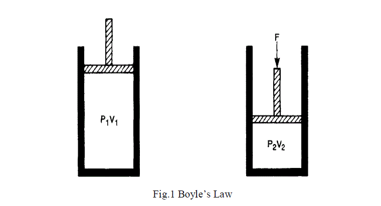 |
| In the following expressions it is important to note that pressures are given in absolute, not gauge, terms and temperatures are given in absolute degrees Kelvin, not in degrees Celsius. If a liter of air at atmospheric pressure and 20° being compressed to three atmospheres gauge pressure, its original pressure was one atmosphere, its original temperature was 293 K and its final pressure is four atmospheres absolute. Pressure and volume are related by Boyle's law. In Fig. 2.1 the volume of gas V1 at pressure P1 (in absolute units, remember). This gas is compressed to volume V2, which will result in a rise of pressure to P2, where" provided the temperature of the gas does not change during the compression. A reduction of pressure similarly leads to an increase in volume. In practice, compression of a gas is always accompanied by a rise in temperature (as is commonly noticed when pumping up a bicycle tyre) and a reduction in pressure produces a temperature fall. |
II. PNEUMATIC COMPONENTS USED FOR SEQUENCING CIRCUIT |
 |
 |
| c) Hoses |
| d) Connectors |
III. CYLINDERS |
| \Pneumatic equipment can be split up into two basic categories of cylinders and valves. Cylinders are the ‘muscles’ of pneumatic systems as they are used to move, hold and lift objects. They can even be used to operate other pneumatic components. Cylinders are operated by compressed air and they covert the stored energy in the compressed air into linear motion. |
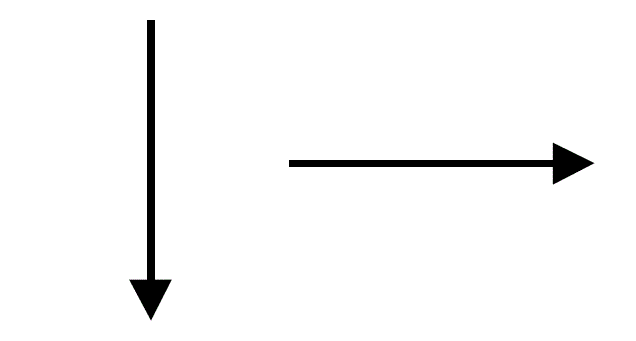
| Linear motion is motion in a straight line: an apple falling from a tree or a sliding door closing is examples of linear motion. We can represent linear motion by arrows like the ones below. |
 |
| Fig. 8 |
| A. General Characteristics Of Pneumatic Cylinder: |
| ïÃâ÷ Diameters 2.5 to 320 mm |
| ïÃâ÷ Stroke lengths 1 to 2000 mm |
| Available forces 2 to 45000 N at 6 bar |
| There are two types of cylinder that we will be using: |
| a) single-acting cylinders |
| b) double-acting cylinders. |
| a) Single-Acting Cylinder |
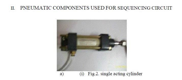
| A single-acting cylinder requires only one air supply. If we supply compressed air to a single-acting cylinder, the air pushes against the piston inside the cylinder and causes it to outstroke. When the piston has fully out stroked it is said to be positive. |
| If we stop the supply of air then the spring inside the cylinder causes the piston to in stroke its starting position and the piston is said to be negative. As this happens, the air inside the cylinder is pushed back out. |
| b) Double-Acting Cylinders |
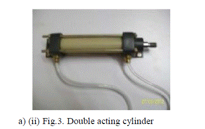
| Double-acting cylinders (DAC) uses the forces of air to move in both extend and retract strokes. They have two ports to allow air in, one for outstroke and one for in stroke. |
| To outstroke a double-acting cylinder we need compressed air to push against the piston inside the cylinder. As this happens, any air on the other side of the piston is forced out. This causes the double-acting cylinder to outstroke. When the piston has fully out stroked it is said to be positive. |
| B. Parts of Pneumatic Cylinder |
| a) Piston |
| The piston is a cylindrical member of certain length which reciprocates inside the cylinder. The diameter of the piston is slightly less than that of the cylinder bore diameter and it is fitted to the top of the piston rod. It is one of the important parts which convert the pressure energy into mechanical power. |
| The piston is equipped with a ring suitably proportioned and it is relatively soft rubber which is capable of providing good sealing with low friction at the operating pressure. The purpose of piston is to provide means of conveying the pressure of air inside the cylinder to the piston of the oil cylinder. |
| Generally piston is made up of |
| ïÃâ÷ Aluminum alloy-light and medium work. |
| ïÃâ÷ Brass or bronze or CI-Heavy duty. |
| The piston is double acting type. The piston moves forward when the high-pressure air is turned from the right side of cylinder. The piston moves backward when high pressure acts on the piston from the left side of the cylinder. The piston should be as strong and rigid as possible. |
| The efficiency and economy of the machine primarily depends on the working of the piston. It must operate in the cylinder with a minimum of friction and should be able to withstand the high compressor force developed in the cylinder and also the shock load during operation. |
| The piston should possess the following qualities. |
| a. The movement of the piston not creates much noise. |
| b. It should be frictionless. |
| c. It should withstand high pressure. |
| b) Cover Plates |
| The cylinder should be enclosed to get the applied pressure from the compressor and act on the pinion. The cylinder is thus closed by the cover plates on both the ends such that there is no leakage of air. An inlet port is provided on the top cover plate and an outlet ports on the bottom cover plate. There is also a hole drilled for the movement of the piston. |
| The cylinder cover plate protects the cylinder from dust and other particle and maintains the same pressure that is taken from the compressor. The flange has to hold the piston in both of its extreme positions. The piston hits the top plat during the return stroke and hits the bottom plate during end of forward stroke. So the cover plates must be strong enough to withstand the load. |
| C). Cylinder Mounting Plates: |
| It is attached to the cylinder cover plates and also to the carriage with the help of ‘L’ bends and bolts. |
| C. Elements Of Pneumatic Cylinders |
a) Air Seal |
| Air seal is used to prevent the leakage of air pressure from the cylinder. Normally it is made up of neoprene rubber. If there are any air leakages in the system, it will reduce the efficiency. |
2.3.2 Wiper Seal: |
| Wiper seal is provided at the entrance of the cylinder to avoid dust materials from the environment. It is made up of neoprene rubber. |
2.3.3 Circlip |
| Circlip is used to protect the out coming of air seal and wiper seal from the cylinder. It is made up of steel. |
2.3.4 “O” - Ring |
| The “O” rings are fitted into the grooves of piston to maintain perfect seal between the piston and the cylinder wall. They are mostly made up of neoprene rubber. |
IV. DIRECTION CONTROL VALVE |
| The following types of direction control valves are used in the circuit: |
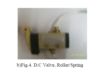
| A. Roller operated direction control valve |
| It consists of a rotor closely fitted in a valve body. Passage drilled in the rotor connect or block the ports in the valve body. It consists of four port pump and tank port. There are various methods to achieve sequencing of pneumatic cylinders. A very simple method is to use mechanically actuated direction control valve with roller as the actuating medium. Roller operated 3/2 direction control valves may be used as the signal elements along with the impulse valves in a predetermined sequence to offer signals to next elements in the series. The effective signals from each of such valves will be transmitted to the respective impulse valve as soon as the particular roller is pressed by a mechanical element. |
| B. Three-way Direction Control Valve |
| A direction control valve whose primary function is to alternatively pressurize and exhaust one working port is called a three way direction control valve. Generally, these valves are used to operate single acting cylinders. |
| A three way valve is one with three ports. An inlet port, a cylinder port, and an exhaust port to a reservoir. The valve is operated by manual, mechanical, pilot or solenoid actuation. |
| C. Pilot Operated Check Valve |
| A pilot operated valve is a design of a two way valve. This type of check valve allows free flow in one direction, but prevents reverse flow until the pilot pressure is applied at the pressure port of valve. |
| When the system pressure through the free flow port overcomes the spring force of the poppet, the poppet is pushed off and it allows one way free flow. |
| The reverse flow is prevented because the fluid pressure pushes the poppet into the closed position. When desired to permit free reverse flow, a pilot pressure is made available at the pilot port. The pilot pressure pushes the pilot piston, which in turn pushes the poppet from its seat. |
| D. Five-Way Direction Control Valve |
| In certain designs of direction control valves, five ports are preferred instead of four ports. This permits the use of either dual supply or dual exhaust. A five port version provides the same basic control of flow paths as a four port version. In addition, dual supply ports permit the use of different pressures for the cylinder movement. Dual exhaust enables easy exhaustion of the valve. |
V.PNEUMATIC TWO HAND SAFETY CIRCUIT DESIGN |
| Our project’s main motto is to press fit a pin to hole using pneumatic devices by economically and to ensure the operator’s safety. So we have designed a simple circuit which is economic and also ensures the operator’s safety. |
 |
VI.ADVANTAGES OF PNEUMATICS |
| A. Simplicity of Design and Control |
| Machines are easily designed using standard cylinders & other components. Machines operate by simple ON - OFF type control. |
| B. Reliability |
| Pneumatic systems tend to have long operating lives and require very little maintenance. Because gas is compressible, the equipment is less likely to be damaged by shock. The gas in pneumatics absorbs excessive force, whereas the fluid of hydraulics directly transfers force. |
| C. Storage |
| Compressed gas can be stored, allowing the use of machines when electrical power is lost. |
| D. Safety |
| Very low chance of fire (compared to hydraulic oil), Machines can be designed to be overload safe. |
VII.DISADVANTAGES OF PNEUMATICS |
| E. Limited pressure |
| High pressure as in hydraulics cannot be attained |
| F. Noisy process |
| Compressors make much noise and exhausting air makes noise. |
VIII.APPLICATION |
| a) Objects that needs hammering or pressing operations. |
| b) Pressing operations at considerable small loads only. |
IX.CONCLUSION |
| Thus the designed and fabricated “sequencing single, double acting cylinder” helps to know how to achieve low cost automation. it is a continuous process .it is very useful for doing drilling, boring, pressing operations. This would boom the mass production industries. The commercial production of this project is feasible economically.by using advanced techniques, the project can be modified and developed. |
References |
|