ISSN ONLINE(2319-8753)PRINT(2347-6710)
ISSN ONLINE(2319-8753)PRINT(2347-6710)
S.Venkatanarayanan, M.R.M. Nanthini
|
| Related article at Pubmed, Scholar Google |
Visit for more related articles at International Journal of Innovative Research in Science, Engineering and Technology
Electricity demand is the major concern in the world today. To meet the demand, the number of natural sources comes under the electricity production. Among that sources wind energy and fuel cell energy is considered in this paper. The Single-Ended Primary- Inductor Converter (SEPIC) and Boost converter are used with the wind energy and fuel cell energy conversion system for the improvement of power generation. The DC-DC converters are typically used in the applications where the output voltage is considerably higher than the input voltage. Basic objective of this paper is parallel connected SEPIC-Boost converters to share the load current. The approach of varying complexity and current sharing performance has been proposed. The advantage of parallel connected power supply is low component stress, increased reliability, ease of maintenance and repair, thermal management. The presence of current sharing loop has been clearly proved for achieving good performance in paralleling of these converters. A MATLAB Simulink has been developed and compared with the single and parallel schemes and also verified the performance. A 230V/250W paralleling scheme is developed for wind and Fuel cell as parallel connected source and verified the results.
Keywords |
| SEPIC converter, Boost converter, Wind energy conversion system, Fuzzy controller, PI controller. |
INTRODUCTION |
| Recent developments and trends in the electric power generation mention an improvement of using renewable energy. Hybridizing the fuel cell and wind power sources provide a realistic form of power generation. Such as both the energy systems are highly reliable due to their unpredictable nature. The wind energy has the capable of supplying the large amounts of power but its presence is highly unpredictable. The wind energy holds the most potential to meet our energy demands. Today, the technology of wind energy and the fuel cell are becoming economically feasible. Often the wind energy sources are widely available energy source in some remote areas. The operation of wind energy is highly depends on the weather condition thus the generation of electricity is variable in time but the fuel cell can produce electricity while being recharged continuously. |
| The renewable energy resources can fluctuate significantly from hour to hour and from season to season and causing variability in the output power. To fulfill the energy requirements during the period of low electricity generation the energy can be stored. The popular way to store energy is batteries, but they loss their energy content rapidly and therefore they can be used only for short time period. Batteries also have the limited life cycle and problems with depth of discharge. |
| Unlike batteries, fuel cells are devices that produce electricity as long as they are supplied with a fuel. They supply on direct electrochemical conservation of a fuel and they are more efficient than internal combustion devices. In order to get usable voltages, the cells are combined in a stack, where they are electrically connected in a series by a bipolar separator plate. Hydrogen based systems offer flexibility in sizing, fuel cells and storage tanks can be adjusted to fulfill various needs and demands. The complexity of the hydrogen based system, to assure a continuous supply to meet the load demand, is very high. |
| The efficiency of utilization of hydrogen in the fuel cell to create electricity is a function of cell voltage. With the increase of voltage, efficiency increases and voltage efficiency decreases. When the source is unavailable or insufficient in meeting the load demands, the other energy source can compensate the demands. In this paper, the input rectifier structure is proposed for the design of wind and fuel cell energy systems. The proposed design is a combination of the SEPIC and Boost converters. |
| Most of the systems in literature use a separate DC-DC boost converter connected in parallel in the rectifier stage. The system requires passive input filters to remove the high frequency current harmonics. The harmonic content in the generator current decreases its lifespan and increases the power loss due to heating. [1] A boost converter combined with a series output module is implemented. A SEPIC-Integrated Boost (SIB) converter provides an additional step-up with the help of an isolated SEPIC converter. [2] The high boost ratio hybrid transformer dc-dc converter is presented. The converter uses the hybrid transformer to transfer the inductive and capacitive energy simultaneously. Using the hybrid linearsinusoidal input current waveforms, the input current ripple and conduction losses are reduced. [3] The pulse width modulated (PWM) quadratic converters are used to achieve the soft computing for both the active and passive switches is presented. In the semiconductor devices there is no additional conduction loss. [4] The converter is to maintain the continuous output current, smaller output voltage ripple, and lower semiconductor current stress is presented. [5] It implemented that both the sources are supplied the load separately or simultaneously, which is depending upon the availability of the sources. Additional filters are not necessary to filter out the high frequency harmonics. [6] The conduction loss is minimized by removing the input bridge diode is presented. |
DC-DC CONVERTERS |
| The DC-DC converters are used to regulate the output voltage and it converts an unregulated dc voltage to a regulated dc output voltage. This regulation can be easily obtained by fixed frequency and the switching device. There are many types of DC-DC converters which are more suitable for many applications. The converters that can be classified into three various groups, in that some converters are suitable for stepping down voltage and some converters are suitable for stepping up the voltage and some converters can be used for either. |
| A. Non-Isolating converter |
| The non-isolating type of converter is generally used where the voltage needs to be step up or step down by a relatively small ratio. The non-isolating converter has five main types of converters, such as, buck, boost, buckboost, Cuk and charge-pump converters. |
| B. Buck converter |
| A buck converter allows stepping up the current and stepping down the voltage. In the buck converter the capacitor can be charged with the energy stored in the inductor. The buck converter has the two modes of operation such as, continuous conduction mode and discontinuous conduction mode. The inductor current never reaches zero in the continuous conduction mode and the inductor current reaches zero at one switching cycle in the discontinuous conduction mode. In the conduction mode, the regulated output voltage has the linear relationship with the output voltage but it is not in the discontinuous conduction mode. |
| C. Cuk Converter |
| Cuk converter is a type of dc-dc converter which allows the output voltage magnitude is greater than or less than the input voltage magnitude. The Cuk converter is derived from the cascading of buck and boost converters and it utilizes capacitive energy transfer. |
| D. Charge-pump Converter |
| A charge pump converter is a type of dc-dc converter which uses the capacitor for energy storage element and can produce the either greater or lower output voltages. |
| The following converters are proposed to design and implement the converters for wind and fuel cell applications. |
| E. SEPIC Converter |
| The Single Ended Primary Inductor Converter (SEPIC) is a type of DC-DC converter and it allows the voltage at its output voltage is greater than the input voltage. The SEPIC converters can both step-up and stepdown the input voltage while maintaining the voltage. |
| The Fig. 1 shows the basic circuit diagram of SEPIC converter, consists an input voltage as IN V , output as load resistance L R , the switch 1 S , and the diode 1 D . When the switch is turned on, the voltage increases and when the switch is turned off the voltage drops. During the steady state operation, by neglecting the ripple voltage, the voltage can be easily determined. |
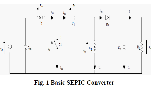 |
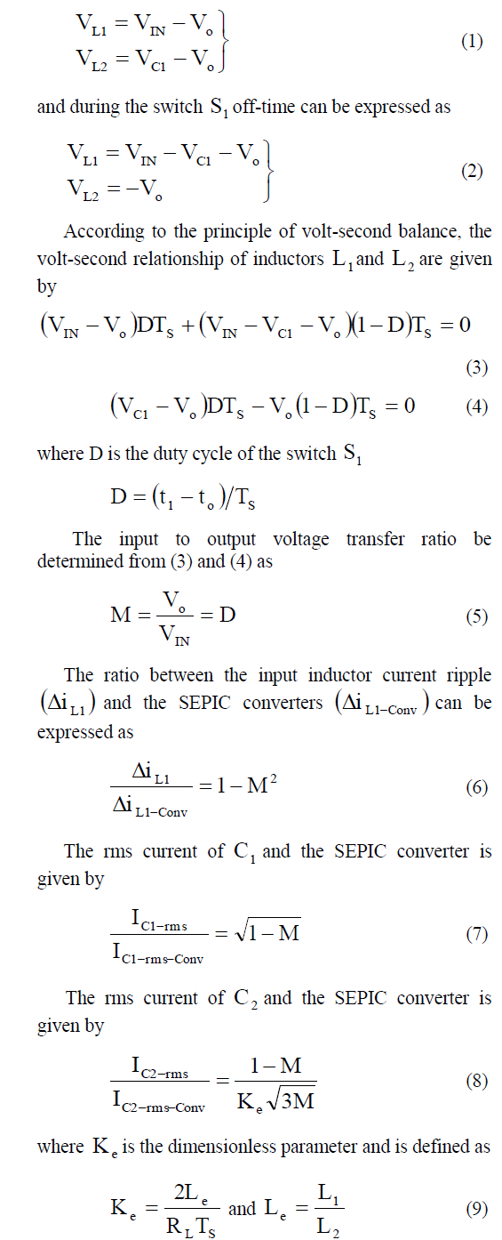
| The input voltage can be represented as IN V . The voltage across 1 L and 2 L during the switch 1 S on-time can be expressed as |
 |
| F. Boost converter |
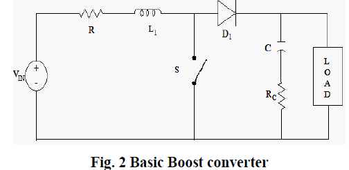
| The boost converter is a DC to DC converter with an output voltage is greater than its input voltage. To reduce the output voltage ripple, the filters are made of capacitors are normally added to the output of the converter. The Fig. 2 shows the basic circuit diagram for boost converter. It is a non-isolated power stage topology. The boost converter is also known as step-up converter. The boost converter has the tendency of the inductor to resist changes in the current by creating and destroying the magnetic field. The output capacitor supplies the entire load current from the rest of the switching cycle. When the switch S is closed the current flows through the inductor in clockwise direction and the inductor stores some energy by generating the magnetic field and the polarity of an inductor is positive. When the switch S is open, the current will be reduced. |
 |
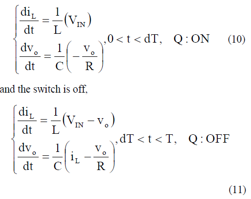
| When the switch S is on, the following are the state space equations, |
 |
| Since the output voltage is greater than the input voltage, the input current which is also the inductor current is greater than the output current. |
ENERGY CONVERSION SYSTEM |
| A. Wind Energy Conversion System |
| Wind power is the conversion of wind energy into a useful of energy, such as using wind turbines as electrical power and using wind mills as mechanical power. The wind power is derived from the conversion of wind into electricity. The various types of wind generators are classifies as |
| (i) Vertical Axis Wind Turbine |
| (ii) Horizontal Axis Wind Turbine |
| 1) Vertical Axis Wind Turbine: The Vertical Axis Wind Turbine (VAWT) have rotor shaft and it can be arranged vertically. They are difficult to mount on towers i.e., it is installed nearer to the base on which they rest and it can be easily accessible for mechanical components. |
| 2) Horizontal Axis Wind Turbine: The Horizontal Axis Wind Turbines (HAWT) has the rotor shaft and the electrical generators are at the top of the tower. The tower is usually pointed into the wind. Most of the small wind turbines are pointed by a simple wind vane and the large turbines are generally used as a wind sensor coupled with servo motor. Turbine blades are made stiff to prevent the blades from high winds. The blades are placed in front of the tower and are sometimes it tilted up a small amount. |
| B. Fuel cell energy conversion |
| A fuel cell is an electrochemical energy conversion device that converts hydrogen and oxygen into electricity, heat, and water. It is very much like a battery that can produce electricity while being recharged continuously. Fuel cells are many types, but they consist of anode (negative side), the cathode (positive side) and an electrolyte which allows the charges to move between the two sides of fuel cell. |
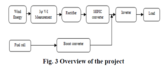 |
SIMULATION RESULTS |
| The simulation results from MATLAB are given to verify that the proposed design and model can support the individual and simultaneous operation. The parameter values of the converter are for the design example is given in Table. 1. |
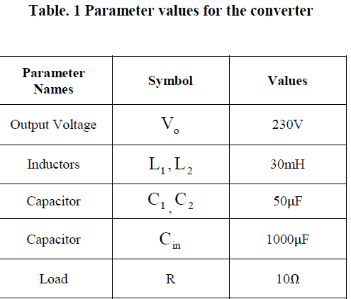 |
| Table. 1 shows the parameter values for the SEPIC converter and the Boost converter. |
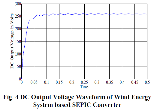
| The Fig. 4 represents the DC output voltage waveform of wind energy system based SEPIC converter with respect to time verses output voltage. |
 |
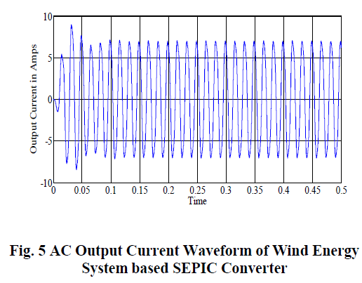
| The Fig. 5 represents the AC output current waveform of wind energy conversion system based SEPIC converter with time verses output current. |
 |
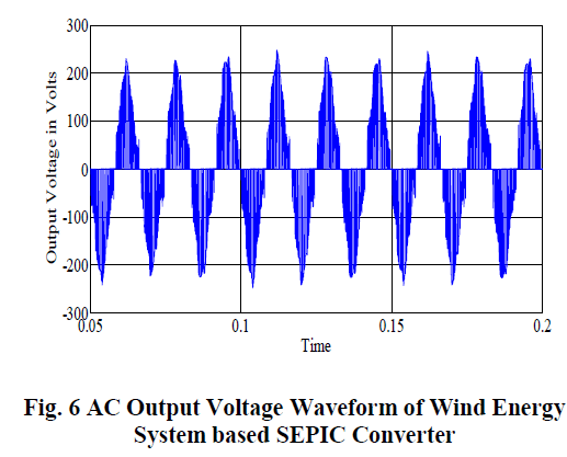
| The Fig. 6 represents the AC output voltage waveform of wind energy conversion system based SEPIC converter with time verses output voltage. |
 |
 |
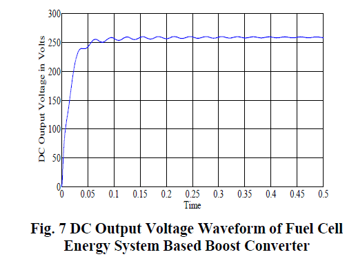
| The Fig. 7 represents the DC output Voltage waveform of fuel cell energy system based boost converter with respect to time verses output voltage. |
 |
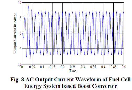
| The Fig. 8 represents the AC output current waveform of fuel cell energy based boost converter with time verses output current. |
 |
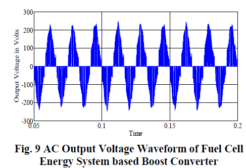
| The Fig. 9 represents the output voltage waveform of fuel cell energy based boost converter with time verses output voltage. |
 |
| A. Advantages of Combining The Converters |
| The efficient DC-DC converter is formed by combining SEPIC and boost stages and controlling the switches to provide a pass-through zone such that when the value of the input is close to the output no switched-mode processing occurs. Efficiency is improved throughout the entire range of operation. |
CONCLUSION |
| The PI controller and the Fuzzy Logic controller are proposed to implement the wind energy conversion system and fuel cell energy conversion system. Both converters are efficiently used to improve the system efficiency and voltage profile improvement. High frequency harmonics are filter out without using any additional input filters. Both the renewable energy sources can be step up and down the voltage. |
References |
|