In this paper, an implementation of Selective Harmonic Elimination Pulse Width Modulation (SHEPWM) as applied to a single phase AC chopper using Generalized Hopfield Neural Network (GHNN) is designed and implemented. The objective of this paper is to eliminate 5, 7, 11, 13 th order harmonics in the output voltage waveform of the AC chopper while retaining fundamental component to the desired value. The switching angles corresponds to the above objective are obtained by solving a set of non-linear algebraic transcendental equations. The problem is redrafted as an optimization problem and it is solved by using GHNN. An energy function is formulated for the above problem and a set of differential equations describing the behavior of GHNN were formed by using the derived energy function. These set of differential equations are stiff in nature and it is numerically solved by the semi-implicit midpoint rule based extrapolation method with suitable initial conditions. The initial conditions are obtained from a look up table. A MATLAB simulation was carried out and the FFT analysis of the simulated output voltage waveform confirms the effectiveness of the proposed method. Hence, the proposed method proves that it is much applicable in the industrial applications.
Index Terms |
| GHNN- Generalized Hopfield Neural
Network, ANN-Artificial Neural Network, SHEPWMSelective
harmonic elimination pulse width modulation,
FFT-Fast Fourier Transform |
INTRODUCTION |
| AC voltage controller converts fixed magnitude ac into
variable magnitude ac without any change in the frequency.
AC voltage controllers have been widely used in
applications such as soft starting of induction motors and
speed control of pumps, industrial heating, line
conditioners, and lighting dimmers. For power transfer in
AC voltage controller mainly two types of control are
normally used. They are on-off control and Phase angle
control. In on-off control, the source is connected to load
for n integral cycles and disconnected from load for m
integral cycles. As the source connected to the load at the zero crossing of the input voltage and turn-off occurs at
zero current, hence supply harmonics and radio frequency
interference are very low. So it is used for heating loads.
However, sub harmonic frequency components may be
generated that are undesirable as they may set up sub
harmonic resonance in the power supply system, cause
lamp flicker, and may interfere with the natural frequencies
of motor loads causing shaft oscillations. |
| In phase angle control, switches connect the load to the
ac source for a portion of each cycle of input voltage.
However, the main disadvantage of ac voltage controllers
with phase angle control is the introduction of objectionable
harmonics in the load voltage waveforms, particularly at
reduced output levels. Therefore, it suffers from poor power
factor, high lower order harmonic content in both of load
voltage and source current. |
| The problems introduced by phase angle control or on-off
control method can be overcome by pulse width modulation
techniques. In pulse width modulation (PWM) control,
the harmonic distortion can be reduced and the power factor
can be improved by controlling the switching instants.
There are two methodologies by which pulse width
modulation can be achieved. One method is by the use of an
explicit carrier based and other the method is carrier less
method. In carrier-based method, a high frequency
triangular carrier signal is compared with a reference signal
gives the required gating signal to trigger the switches in
the ac voltage controller. The significant example for
carrier based PWM is sinusoidal PWM. In carrier less
method, the switching instants required for the pulse
generation are determined by the solutions obtained by
solving a set of equations using from numerical methods or
any of the optimization techniques. The significant example
for carrier less PWM is SHEPWM technique [1-2]. |
| The Selective Harmonic Elimination (SHE) PWM
technique is a widely used PWM method for the
elimination of lower order harmonics and to retain the
fundamental component at the desired level in the output
voltage of single-phase ac-ac chopper. The higher order
harmonics are eliminated by using passive filters or by the
inherent low pass nature of electrical machines. The
switching instants on the time axis are obtained by solving a
set of nonlinear algebraic transcendental equations by two
popular approaches. In the first approach, numerical
iterative techniques such as the Newton Raphson method
are proposed. The second approach views the problem as an
optimization problem rather than an analytical problem.
This approach involves forming of an objective function
using the analytical equations, and then the objective
function is minimized to get the solutions. Various
optimization techniques have been adopted for minimizing
the objective function such as Genetic Algorithm, Particle
Swarm Optimization and Ant Colony Algorithm etc [3-4].
Nevertheless, these optimization techniques are difficult to
be implemented in hardware and hence their real time
implementation is a tedious one. |
| Neural network based optimization approach is also used
for solving the above problem, in which feed forward
artificial neural network [Back Propagation Network] is
used for selecting suitable switching instants for the
elimination of low-order harmonics and to retain the
fundamental at the desired level. A non-deterministic
method is used to solve the system of nonlinear algebraic
transcendental equations to obtain the data set for the ANN
training. This method also provides a set of acceptable
solutions in the space where solutions are not obtained by
analytical methods.The advantage of neural network based
approach is it can be realized in hardware and hence real
time implementation is possible. |
| In this paper, an implementation of selective harmonic
elimination (SHEPWM) using Generalized Hopfield Neural
Network (GHNN) to minimize 5th, 7th, 11th and 13th order
harmonics while retaining the desired fundamental in a
single phase AC-AC chopper is discussed. Generalized
Hopfield Neural Network (GHNN) is a continuous time
single layer feedback network. Figure.1 shows the block
diagram of the proposed method. For the given normalized
fundamental output, voltage the GHNN block is used to
calculate the switching instants. These switching instants
are given to the PWM generator, which generates the
required gating signals to the chopper. |
 |
| The paper has been organized as follows: Chapter II
gives an overview of GHNN and its application to the
solution of nonlinear algebraic transcendental equations.
Chapter III describes the proposed method of application of
GHNN to SHEPWM in AC Chopper. Chapter IV explains
the MATLAB simulation. Chapter V Gives results of
simulation. Finally, conclusions of this work are
summarized in Chapter VI. |
II. GHNN AND ITS APPLICATION TO THE SOLUTION
OF NON-LINEAR ALGEBRAIC TRANSCENDAL
EQUATION |
| A.Overview of GHNN |
| The continuous time single layer feedback networks are
called “gradient type networks” in which time is assumed a
continuous variable. Gradient type neural networks are the
Generalized Hopfield Neural Networks (GHNN) in which
the computational energy decreases continuously with time.
The evolution of the system is in the general direction of
the negative gradient of the energy function. The transients
of the GHNN converge to one of the stable minima in the
state space. The generalized electrical architecture of the
GHNN is shown as in Figure.2 |
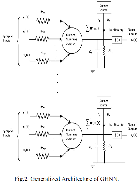 |
| It consisting of an interconnection of n’ neurons, each
one of which is assumed to have the same mathematical
model described in equations (1) and (2). Where Rj
represents leakage resistance, Cj represents leakage
capacitance and φ (.) represents activation function. In
physical terms, the synaptic weights Wj1, Wj2,…Wjn
represent conductance’s, and the respective inputs
x1(t),x2(t),…., xn(t) represent potentials; n is the number of
inputs. These inputs are applied to a current summing
junction characterized by low input resistance, unity current
gain and high output resistance. It thus acts as a summing
node for the input currents. The total current flowing
toward the input node of the nonlinear element(activation
function) in Figure.2 is therefore where the
first(summation) term is due to the stimuli x1(t),x2(t),….,
xn(t) acting on the synaptic weights (conductances) Wj1,
Wj2,…Wjn respectively, and the second term is due to the
current source Ij representing an externally applied bias. |
 |
| Let uj(t) denote the induced local field at the input of the
nonlinear activation function. We may then express the
total current flowing away from the input node of the
nonlinear element as follows: |
 |
| Where the first term is due to the leakage resistance Rj
and the second term is due to leakage capacitance Cj. From
Kirchoff’s current law, we know that the total current
flowing toward any node of an electrical circuit is zero. By
applying Kirchoff’s current law to the input node of the
nonlinearity. We may define the dynamics of the network
by the following system of coupled first-order differential
equations by ignoring interneuron propagation time delays. |
 |
| An assumption is made that the activation function
relating the output xj(t) of neuron ‘j’ to its induced local
field uj(t) is a continuous function and therefore
differentiable. A commonly used activation function is the
logistic function. |
 |
By using conventional methodology one can see that the
derivative for the proposed energy function is always less
than or equal to zero, i.e.  and energy of the system is
thus bounded. and energy of the system is
thus bounded. |
| B. Application of GHNN to the solution of nonlinear
equations |
| Let us consider a set of nonlinear algebraic equations
given below: |
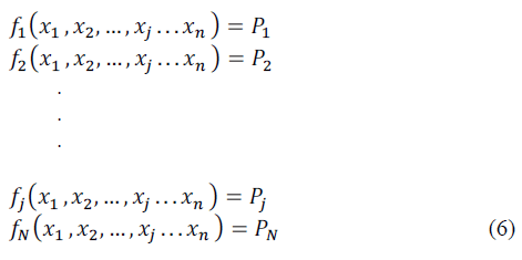 |
| In the above equations fj(.) is a function of variables
x1,x2,…,xj…xn ∈ ℜ and Pj∈ ℜ is a real constant. Our
objective is to find the values for variables x1,x2,…,xj…xn
such that it satisfies the equation (8).To obtain the solution
using proposed approach an energy function has to be formulated. The energy function for the above set of
equations is derived as follows: |
 |
| Equations (9) and (10) have been used for designing the
proposed network. The number of neurons in network is
equal to the number of variables whose value is to be
determined. In the given problem, we have ‘n’ number of
variables and hence the network should have ‘n’ number of
neurons. The network dynamics are governed by following
differential equations: |
 |
| Where u j is the net input to the jth neuron in the network
and xj is its output. In this application, the function φ(.)
is a linear input – output transfer function for the ‘j’ the
neuron. Calculating the partial derivatives of Equation (10)
with respect to unknown variables x1,x2,....,xj...xn and
colleting, the terms of identical order will results in
Hopfield equations like form. The coefficients and
constants in the available expression give the weights and
bias values for the network respectively. A suitable
numerical algorithm is used to solve the differential
equations governing the network dynamics. |
III. APPLICATION OF GHNN TO SHEPWM |
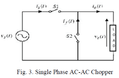
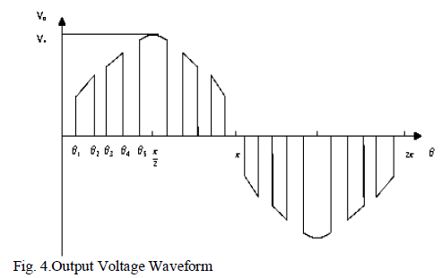
| A standard single phase AC-AC Chopper is shown as in
Fig. 3 is used to generate the waveform shown as Fig.4. |
 |
 |
| A.Formulation of the Transcendental Equations |
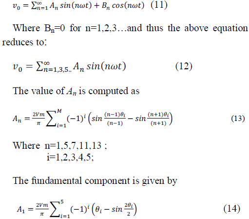
| The Fourier series expression for the output voltage
waveform shown as in Figure. Is given dy the following
equation |
 |
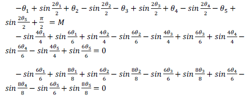
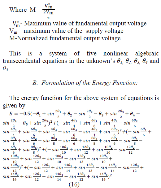
| Given a desired fundamental voltage V1 and for the
elimination 5,7,11 and 13th harmonics, the problem here is
to determine the switching angles θ1, θ2, θ3, θ4 and θ5 such
that |
 |
 |
 |
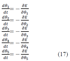
| The differential equation governing the behavior of the
network dynamics is calculated using energy function and
is given as follows: |
 |
| C. Solution of Non-Linear Algebraic Transcendental
Equations |
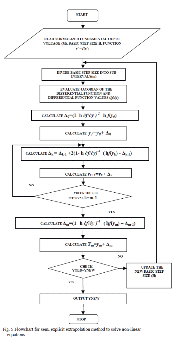
| The flow chart of the semi-implicit mi point rule based
extrapolation method to solve a set of five non-linear
algebraic transcendental equations[6] is shown as in Fig.5. |
 |
IV. SIMULATION |
| In this section the matlab simulation and implementation
using the derived mathematical model is explained. |
A.MATLAB/SIMULINK SIMULATION |
| The MATLAB/SIMULINK simulation diagram of the
proposed system is shown as in Fig.6. It consist of three
main sections of main power circuit, switching section and
load . The power circuit of single phase AC-AC Chopper
simulation model is formed by using main power module
and freewheeling module, both consists of four diodes and
one IGBT. The switching section generates switching
angles for the various normalized fundamental output
voltages that lies in between 0.02 and 1.16. |
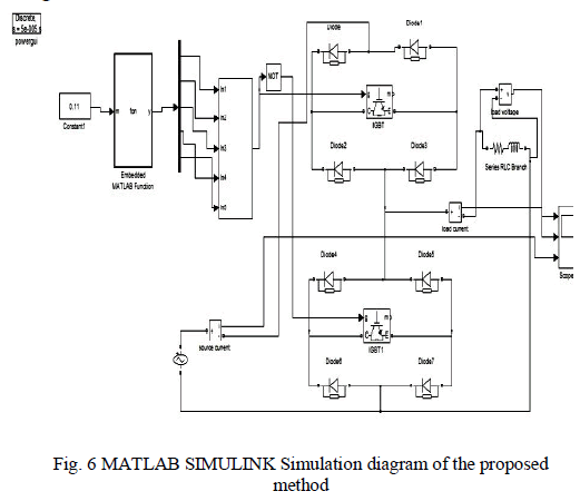 |
| The switching section consists of two sub systems. One
of these two subsystems is a MATLAB embedded
functionblock1 contained the m file of the GHNN, which
accepts different normalized fundamental output voltages
and thus provides the required switching instants θ1, θ2, θ3,
θ4 and θ5. The switching instants derived are in radians. The
second subsystem consists of a triangular wave generator
and a gating system. The triangular wave is synchronized
with the supply voltage. The synchronization is achieved by
detecting the zero crossing point of the supply voltage. The
main line derived AC sample is first attenuated and then fed
to the zero cross detector. At the front end there are two
diodes connected anti parallel for limiting the voltage to be applied across the input terminals of the comparator. At the
output of the comparator, a train of positive and negative
half cycles of square wave is obtained. The positive half
cycles of square pulses are separated by rectification
process. The rectified positive half cycles is used as timing
references for the switching instants of the positive half
cycle of the AC chopper. The positive square wave is then
phase shifted by 180 degree, by a transistorized phase
inverter to be used for timing reference for the switching
instants of the positive half cycle of the AC chopper. The
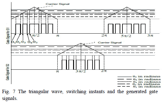
triangular wave generator generates a triangular wave that
rises linearly in 5 ms from 0 to 1.57 radians and falls to zero
at the same rate at a frequency of same as that of the
chopper output frequency. A comparison of this triangular
wave against the switching instants produced the embedded
MATLAB function block gives the ‘on and off’ pulses
required to drive the IGBT switches as shown in Fig.7. The
train of ‘on and off’ pulses thus produced are used to drive
main power module of chopper The same train of pulses
just delayed by 10 milliseconds drives freewheeling module
of chopper. |
 |
V. SIMULATION RESULTS AND DISCUSSIONS |
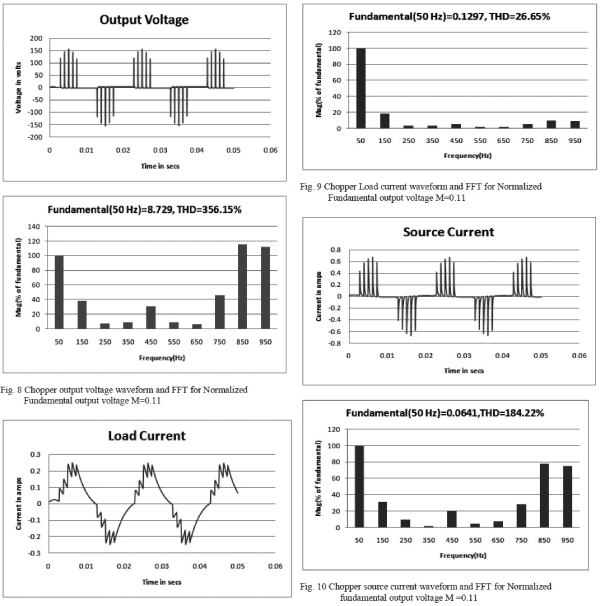
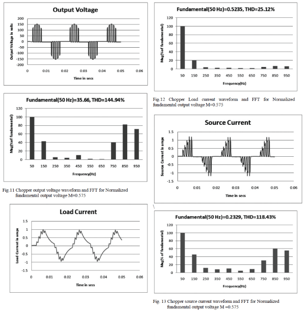
| The AC Chopper was studied with a AC supply of 110V
rms and checked with a RL load of R=50Ω and
L=150mH.The simulated results for Chopper output voltage
waveform and source current for different normalized
fundamental output voltages and the corresponding FFTs
are shown from Fig.8 to Fig.16 |
A. MATLAB/SIMULINK SIMULATION RESULTS |
 |
 |
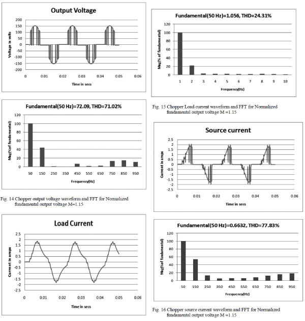 |
| It can be noted that the MATLAB simulation results reveals
that the 5th, 7th,11th and the 13th order harmonics are
minimized and the desired fundamental is retained for randomly selected modulation indices of 0.11, 0.575 and
1.15.The results of MATLAB simulation is shown in Table-
I. |
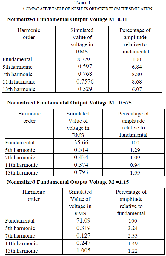 |
| From table-I, it can be noted that the MATLAB
simulation results confirms that the 5th, 7th,11th and the
13th order harmonics are minimized and the desired
fundamental is retained for randomly selected Normalized
fundamental output voltage of 0.11, 0.575 and 1.15. |
VI.CONCLUSION |
| In this paper an implementation of SHE PWM to
minimize the 5th, 7th, 11th and 13th order harmonics in the
output voltage waveform of single phase AC-AC Chopper
while retaining the desired fundamental is discussed. In this
paper, the initial conditions for solving the differential equations governing the behavior of GHNN are obtained
from a look up table. More over this paper uses semiimplicit
midpoint rule based extrapolation method for
solving the differential equations, which is faster than any
other implicit algorithm. Therefore, the dynamic response
of the system is faster. The efficiency of the proposed
technique has been validated using simulation The potential
application or use of the proposed algorithm
implementation is in a very wide range of low, medium,
and high power applications including residential
applications, renewable energy systems, distributed
generation, and automotive. The proposed method produces
consistent results and highly reliable, hence it has potential
to solve varieties of optimization problems |
References |
- Muhammed H. Rashid, ”Power Electronics Circuits, Devices andApplications”, Third Edition, Dorling Kindersley of India, New Delhi-17,2011,pp-265-280.
- Flores-Arias.J.-M. ; Moreno-Muñoz.A. ; Domingo-Perez.F. ; Pallares-Lopez, V. ; Gutierrez, D."Voltage regulator system based on
- PWM ACchopper converter” IEEE International Symposium on IndustrialElectronics (ISIE), 2011, Page(s): 468 – 473
- Sundareswaran.K. ;Kumar.A.P. ” Voltage harmonic elimination inPWM AC chopper using genetic algorithm” Electric Power Applications, IEE Proceedings Volume.151 , Issue.1, Jan. 2004, Pages:26 – 31
- Sadr, S.M. ,Monfared, M. , Mashhadi.H.R. “Application of PSO forselective harmonic eliminationin a PWM AC/AC voltage regulator” ,International eConference on Computer and Knowledge Engineering(ICCKE),2012 Page(s): 62 – 65
- James A. Anderson, “An Introduction to Neural Networks” PrenticeHall of India, New Delhi-1, 1998, pp. 401-416.
- H.Rosenbrock; “Some general implicit processes for the numericalsolution of differential equations”, :Indian Institute ofTechnology,Guwahati. On 1st June 2013
|