most oil pumping units (OPUs) have been using manual control in the oilfield. In this paper, network based automatic control is proposed for OPU management. This proposed network can sequentially realize automatic data sensing, automatic malfunction detection, remote data transmission, intelligent data organization and management, automatic malfunction warning, automatic stroke adjustment and state report via GSM short message service (SMS). Specifically, the proposed network based automatic control system contains four parts: 1) the first level sensors (FLS) for data sensing; 2)the developed intelligent sensors (ISs), which are the second level sensors, for data storage and elementary processing;3) a communication protocol for data transmission; and 4)a software-based network center for data processing, data management, malfunction detection, remote stroke adjustment, GSM SMS and so on. In this paper, we focus on describing the IS design and reporting the elementary experiment results of the proposed system at the oil well.
Index Terms |
| Wireless Sensor Network, intelligent. |
INTRODUCTION |
| In this project, a sensor network based intelligent system isproposed and applied for remote oilwell health monitoring
andautomatic oil-pumping control. The motivation of developingthis system is that due to the special nature of oil
explorationand oil drilling, the majority of oil pumping units (OPU1) are spread over barren hills, mountains and
deserts, and theexisting oil-pumping systems still adopt manual control. Existingmanual control systems have three
evident drawbacks. |
| The OPU administrators have to frequently go to the oilfieldto check the OPU status and collect its health
analysis data.For the sake of the harsh oilfield environment, especially in thewinter when it is chilly and snowing
overspreading the wholeoilfield, it is quite difficult to effectively manage and maintain allOPU manually. |
| Power consumption for OPU is huge duringtheoil-pumping process. Especially in barren oilwells, powerwastage is
extremely high because each oil-pumping is not filledunder such condition and thus oil production greatly drops
eventhough the OPU pumping stroke remains high. And , sincean administrator has to take charge of a number of
oilwells, anOPU malfunction is difficult to locate and repair in a reasonabletime, which causes an oil production drop. |
| In this project is used to monitor the parameters of the oifield. When we are filling the oil tank at that time diffrent
parameters affect on the control system. first parameter is the power requiremet is high due motor get started. Also oil
pressure means oil flowing through the pipe .Aslo it is important to monitor the oil level of the tank. All information it
need to send to control station because we want to monitor the parameters. |
| The parameter information is send to the control station by using Zigbee nodes. Zigbee is the new wireless
technology it uses 2.4 GHz frequency band with having IEEE 802.15.4a protocol.When we are receiving this
information from the wireless sensor network we want to minitor the parametrs & control this parameter wirelessly
form remote station. For this application it should have to maintain the database for it to keep record of the
parameters.[1] |
II. IMPLEMENTAION |
| A. Network TopologyAnd System Description |
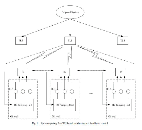
| Fig.1 shows the proposed network topology, i.e. the whole system architecture, which includes the FLSs, the second
level sensors, i.e. developed intelligent sensors (ISs) and the network center. This proposed network can guarantee that
one network center can simultaneously manage and maintain hundreds In Fig.1, FLSs are utilized for data sensing from an OPU, whichconvert all measurements into electrical signals and transmit them into the IS. When IS received sensing
data, on one hand, IS may relay sensing data to network center by wireless communication; on the other hand, IS may
elementarily process sensing data, report significant malfunction and output typical information, such as the maximal,
minimal and average sensing data and so on. The |
| The detailed function of IS are illustrated as follows of |
| • Elematary processing of sensing data, such as calculating the maximum value, the minimum value and the average
value; |
| • Wireless transmission of sensing data via a developed OPU communication protocol; |
| • Power efficiency via a frequency converter since the lower the power frequency, the slower the motor, the smaller the
stroke of OPU; |
| • Significant malfunction detection, such as missing phase and overcurrent; |
| • Relay protection, where the power will be cut off when phase is missing or overcurrent occurs; |
 |
| B. Communication between FLS and IS |
| A group of FLS in our proposed system consists of a load sensor, an angular sensor, a voltage sensor, a
current sensor and an oil pressure sensor while the IS mainly contains two components: the designed control board and
the frequency converter. Five kinds of sensing data from FLS are imported to its IS. The IS usually transmits oil well
static parameters (At the initial stage), significant malfunction reports (if necessary), dynamic sensing data and
elementary processing data directly to the TLS. As a special case, when the wireless communication between the IS
and the TLS fails, the IS sends data to its adjacent IS for relay transmission up to the TLS.[2] |
| On the other hand, when acquiring a pumping stroke adjustment command from the TLS, the control board
executes this command by transporting the corresponding control logic down to the frequency converter [2], [3], which
has the capability of changing power frequency as well as the OPU’s pumping stroke. |
III.HARDWARE DESIGN FORINTELLIGENT SENSOR |
| A. Sensing Module: |
| Sensing module contains load sensor,angular sensor, voltage sensor, current sensor, oil pressure sensor and the
corresponding conditioning circuit, Load sensor is employed to acquire instantaneous load of slick rod. Angular sensor
is used for measuring the instantaneous inclination of OPU crossbeam. Voltage sensor and current sensor are used for
measuring the instantaneous voltage and current of power supply, respectively. Oil pressure sensor is used for
measuring the oil pressure of oil pipe. |
| Specifications and measuring accuracy of FLSs are illustrated as follows: |
| Load sensor: 0 − 150kN and accuracy 5% ; |
| Angular sensor: 0 − 2π and accuracy 5% ; |
| Voltage sensor: 0 − 500V and accuracy 5%; |
| Current sensor: 0 − 50A and accuracy 5% ; |
| Oil pressure sensor: 0 − 150kN and accuracy5%. |
| B. Relay Protection Module: |
| Relay protection module consists of circuit breaker, contactor and connection circuit as. This module is used for
detecting the motor |
| C. Interface Module: |
| Interface module includes 4 × 4keyboard, 128 × 64 LCD, indicator lights, a buzzer, power switch, start button and
stop button. This module is the interface between staff and IS, by which OPU can be started or stopped, the stroke of
OPU can be changed, OPU parameters can be presetted, sensing data can be inquire dand the malfunction information
can be acquired. |
| D. Frequency Converter Module: |
| Frequency converter module contains frequency converter and a braking resistor. On one hand, this module can realize
soft boot for motor, which reduces inrush to OPU and motor. On the other hand, this module can adjust the motor speed
according to the received command from CPU so that the stroke of OPU is adjusted and the power is saved. |
| E. Wireless Communication Module: |
| Wireless communication module is made of a radio station and a Yagi antenna.9-pin RS232 serial is utilized for the
connection between CPU and radio station. Sensing data and OPU parameters are sent to network center by using this
serial and Yagi antenna.[2][3] |
IV. SYSTEM DESCRIPTION FLS and IS |
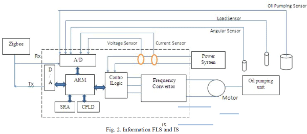
| In the Fig.2 FLSs in our system contain load sensor, angular sensor, voltage sensor, current sensor and oil pressure
sensor while IS includes control board and frequency converter. Sensing data via FLSs are input into IS. IS
automatically transmits sensing data, OPU parameters and the detected malfunction to network center per 20 minutes
unless certain significant malfunction occurs so that the power is cut off. On the other hand, when IS acquires the
command from network center by wireless communication. |
 |
 |
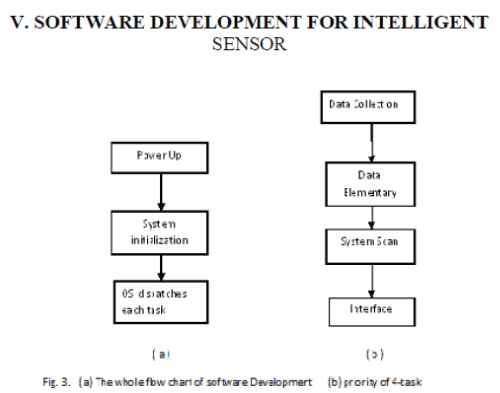
| As shown in Fig.3 (a), once power up, the system starts hardware and software initialization. After system
initialization, OS will dispatch certain one of our 4tasks. Fig.3 (b) illustrates the priority of 4 tasks, where data
collection has the highest priority, next is data elementary processing, followed by system scan and last is interface. |
VI. CONCLUSION |
| By using zigbee technology it is possible to send as well as receive all the information without any intervation of any
envoronmental condition. That means ther is no problem of line of sight. By ausing ARM7 microcontroller the system
response we are getting is very good.In this paper, a sensor network based oilwell remote healthmonitoring and
intelligent control system was proposed forOPU management in the oilfield. This proposed system consistsof threelevel
sensors: the FLS, the IS and the TLS. TheFLS have been used for an oilwell’s data sensing, includinga load
sensor, an angular sensor, a voltage sensor, a current sensor and an oil pressure sensor for each oilwell. |
ACKNOWLEDGMENT |
| The goal of this paper is to design “Design and Implementation Wireless Sensor Network”. The function has been
realized successfully. I want to give my whole sincere to my supervisor and grateful appreciation to Prof. Miss. S.G.
Joshi as my supervisor of dissertation work; she tried her best to help me. Without her help and guidance I cannot bring
the theories into practice. On the other hand, I want to thank all my family members and friends for their always
support and spiritual motivation. |
References |
- Donglin Wang, Member, IEEE, Renlun He, Jiangqiu Han, Michel Fattouche, and FadhelM.Ghannouchi,Fellow,IEEE,âÃâ¬Ã Sensor Network Based
- Oilwell Health Monitoring and Intelligent ControlâÃâ¬ÃÂ, IEEE SENSORS JOURNAL, VOL. 12, NO. 5, MAY 2012,pp.1326-1339.
- KAIYUANMENG ; PENG YANG ; QINGNIAN CAOâÃâ¬Ã DESIGN FOR THE NETWORK NODE OF OILFIELD, MONITORING SYSTEM BASED ONZIGBEETECHNOLOGYâÃâ¬ÃÂ,MULTIMEDIA INFORMATION NETWORKING AND SECURITY (MINES), 2012.
- Ting He, S.-H. Gary Chan, and Chi-Fai Wong, Hong Kong University of Science and Technology,âÃâ¬Ã HomeMesh: A Low-Cost Indoor Wireless
- Mesh for Home NetworkingâÃâ¬ÃÂ,CONSUMER COMMUNICATIONS AND NETWORKING, IEEE Communications Magazine December 2008,pp.79-85.
- T. Becker, M. Kluge, J. Schalk, K. Tiplady, C. Paget, U. Hilleringmann, and T. Otterpohl, âÃâ¬ÃÅAutonomous sensor nodes for aircraft structural healtmonitoring,âÃâ¬Ã IEEE Sensors J., vol. 9, no. 11, pp. 1589âÃâ¬Ãâ1595, Nov. 2009.
- D. G. Senesky, B. Jamshidi, K. Cheng, and A. P. Pisano, âÃâ¬ÃÅHarsh environment silicon carbide sensors for health and performance monitoring of
- aerospace systems: A review,âÃâ¬Ã IEEE Sensors J., vol. 9, no. 11, pp. 1472âÃâ¬Ãâ1478, Nov. 2009.
|