ISSN ONLINE(2319-8753)PRINT(2347-6710)
ISSN ONLINE(2319-8753)PRINT(2347-6710)
Ajay Sankar N R, Dr. S. Sankar
|
| Related article at Pubmed, Scholar Google |
Visit for more related articles at International Journal of Innovative Research in Science, Engineering and Technology
Air conditioning demand is rapidly increasing in many parts of the world, especially in moderate climates. Air conditioners and refrigerators are the only equipment’s consumes more electricity say 70% in the household articles. This results in a dramatic increase in electricity demand on hot summer days, which causes an unwanted increase in the use of fossil fuel and nuclear energy, leads to global warming and air pollution. This paper describes the usage of vapour absorption air conditioning systems using solar thermal energy. In this system an electric generator is replaced by solar thermal collectors for heating the refrigerant called LiBr-Water. During this study an atmospheric temperature, fluid temperature at the collector and the temperature of space to be conditioned were measured to find out the COP of the system. The specifications of the entire system components are arrived based on the design calculations recommended by ASHRAE. The experimental results shows that there is a drastic decrease in the dry bulb temperature when compared with outside dry bulb temperature. The main objective of this study is to reduce the electricity consumption by introducing solar thermal energy.
Keywords |
| Solar Heating, Solar Cooling, Electrolux, Vapour Absorption Cycle, LiBr-Water Solution |
INTRODUCTION |
| Worldwide, most cooling and refrigeration systems are powered by electricity. Due to growing cooling and refrigeration demand, peak-load problems in the electricity grid in countries with high cooling load are forever increasing. Thermally driven cooling technologies represent promising alternatives and are set to play a key role in the efficient conversion of energy in the field of building air-conditioning and refrigeration. Today, these technologies are used mainly combined with waste heat, district heat or cogeneration plants. But thermally driven cooling cycles can also run with solar thermal energy. In climates where cooling is not required all year round, solar thermal driven cooling systems can also be used for space heating or domestic hot water preparation during periods without cooling demand. |
| A. Background |
| Absorption refrigeration system differs from vapor compression refrigeration system due to utilization of thermal energy source instead of electric energy. In the absorption refrigeration system two working fluids are used: a refrigerant and an absorbent. Among the most applied working fluids are the pair ammonia refrigerant water absorbent (NH3–H2O) and water refrigerant–lithium bromide absorbent (H2O–LiBr). The pair water–lithium bromide is the difficulty to operate at temperature lower than 00C. So it is very much useful to air conditioning systems |
| Hosni I. and Abu-Mulaweh [3], a prototype of a solar water heating system was constructed and tested. The solar collector rotated as the sun position/angle was changing, indicating the functionality of the control system that was design to achieve this task. Experimental measurements indicate that the water in the tank was heated by the solar energy being absorbed by the solar collector. Moreover, the water temperature measurements at different heights in the storage tank show the thermo-siphon effect. Solar water heating utilizing thermo-siphon is attractive, because it eliminates the need for a circulating pump. Results indicate that the design of the thermo-siphon solar water heating system was a success. Furthermore, the experimental apparatus described in this article is a valuable addition to the undergraduate mechanical engineering laboratory. The experimental apparatus is portable, and it can be used as an instructional experimental apparatus for demonstrating basic heat transfer principles and thermo-siphon concept. |
| V Mittal et.al [6], in their work they found out solar absorption air-conditioning has the advantage of both the supply of sunshine and the need for refrigeration to reach maximum levels in the same season. Of the two main technologies of solar cooling systems namely, solar thermal technology and solar cooling technology, the emphasis in this paper is placed on solar cooling technology. Some of the findings of their work are as follows:Among the major working pairs available, LiBr-H2O is considered to be better suited for solar absorption air-conditioning applications.Generator inlet temperature of the chiller is the most important parameter in the design and fabrication of a solar powered airconditioning system.A Single effect system with refrigerant storage has the advantage of accumulating refrigerant during the hours of high solar insolation but the double effect convertible system has a higher overall COP.Many research papers have been published on ammonia-water vapour absorption systems, but an attempt has not been made to analyze the LiBr-Water vapour absorption systems using solar thermal energy, to the best knowledge of the investigator. Therefore, it is imperative to investigate the performance analysis of the LiBr-Water vapour absorption systems using solar thermal energy. |
SOLAR THERMAL COOLING SYSTEM |
| A. Domestic Electrolux Vapour Absorption cycle |
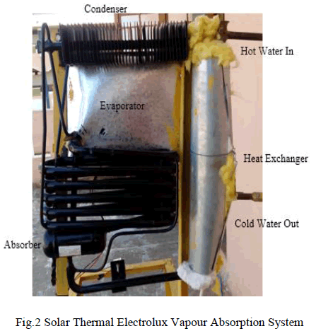
| Fig.1. shows a schematic diagram ofModifiedElectrolux Absorption unit. It is a domestic refrigerator and is the best known absorption type of refrigerator. Here pump is dispensed with. The small energy supply is by means of a heater which may be electric or through solar thermal systems.The principle involved makes use of the properties of gas-vapor mixtures. If a liquid is exposed to an inert atmosphere, it will evaporate until the atmosphere is saturated with the vapor of the liquid. This evaporation requires heat which is taken from the surroundings in which the evaporation takes place. A cooling effect is thus produced. The partial pressures of the refrigerant vapor (in this case water) must be low in the evaporator, and higher in the condenser. The total pressure throughout the circuit must be constant so that the only movement of the working fluid is by convection currents. The partial pressure of refrigerant is kept low in requisite parts of the circuit by concentrating hydrogen in those parts. |
| The unit consists of four main parts - the generator (heat exchanger), condenser, evaporator and absorber. The unit can be run on electricity, solar or gas. The unit consists of a quantity of lithium bromide, water and hydrogen at a sufficient pressure to condense water at the room temperature for which the unit is designed. When heat is supplied to the heat exchanger system, bubbles of water vapour are produced which rise and carry with them quantities of weak lithium bromide solution through the siphon pump. This weak solution passes into the tube, whilst the water vapour passes into the vapour pipe and pass to the condenser. Air circulating over the fins of the condenser removes heat from the water vapour to cause it to condense to liquid water in which state it flows into the evaporator. |
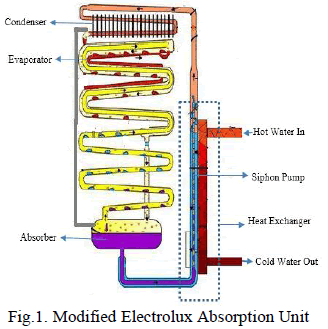 |
| The evaporator is supplied with hydrogen. The hydrogen passes across the surface of the water and lowers the water vapour pressure sufficiently to allow the liquid water to evaporate. The evaporation of the water extracts heat from the space, as described above, thereby lowers the temperature inside the cabin. The mixture of water and hydrogen vapour passes from the evaporator to the absorber. Entering the upper portion of the absorber is a continuous trickle of weak lithium bromide solution fed by gravity from the tube. This weak solution, flowing down through the absorber comes into contact with the mixed water and hydrogen gases which readily absorbs the water from the mixture, leaving the hydrogen free to rise through the absorber coil and to return to the evaporator. The hydrogen thus circulates continuously between the absorber and the evaporator. The strong lithium bromide water solution produced in the absorber flows down to the absorber vessel and hence to the generator system, thus completing the full cycle of operation. The liquid circulation of the unit is purely gravitational. |
 |
| Heat is generated in the generator by the process of absorption. This heat must be dissipated into the surrounding air. Heat must also be dissipated from the condenser in order to cool the water vapour sufficiently for it to liquefy. Free air circulation is therefore necessary over the absorber and condenser. The whole unit operates by the heat applied to the boiler system and it is of paramount importance that this heat is kept within the necessary limits and is properly applied. |
DESIGN AND FABRICATION OF THE SYSTEM |
| A. Design of Solar Collector |
| Here the collector used is parabolic dish type.Taking maximum temperature at the generator, TG=120°C |
| Solar constant (ISC) =1367 W/m2 |
| Extraterrestrial radiation (IO) =1413.5 W/m2(for March) |
| Geographical location of the place where the solar collector was placed; college compound (Latitude =10.74N, Longitude =76.45E) |
| Also the month of operation is assumed to be March (ïÿýïÿý = 0, ïÿýïÿý = 0). Direct radiation reaching the surface at earth is a function of time of the day, latitude location and declination angle. Z is the zenith angle, is calculated thus, |
| Where, γ is the latitude of location, δ is the declination angle and ω is the hour angle |
| cos z= sin(10.74) sin(0) + cos(10.74) cos(0) cos(0) |
| cos z= 0.9824829373 |
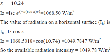 |
| Assume, 50% efficiency due to: - Variance, Collector efficiency, Manual tracking system |
| This implies solar radiation intensity at college compound = 524.89 W/m2 |
| But, practically we get average solar radiation intensity at college compound = 800 W/m2 (ground) |
| Now, reflected intensity (Ri) = 0.8×800 =640 W/m2(Reflectivity of magnesium coated aluminum sheet=0.8) |
| Then, Heat required at collector receiver |
| Qi =5 x 4.18 x (120-30)/3600 |
| Qi = 0.523 kW = 523W |
| Area of parabolic dish (Ad) = 523/640 =0.81m2 |
| Take depth (h). h=0.3m |
 |
| By trial and error; |
| r=0.5m, D=1m |
| Focal length (F) =r2/4h = 0.52/4×0.3 =0.208m |
| Ideal operating temperature required at generator=90°C-120°C |
| B. Design Considerations of Electrolux Domestic Unit |
| The design considerations of domestic Electrolux Vapour Absorption Air Conditioning System are the following, Generator (bubble pump) |
| Length=25cm, Diameter=2cm |
| Condenser |
| Length=32cm, Diameter=1.4cm |
| Absorber (Vessel) |
| Length =12.5cm, Diameter=5.8cm |
| Evaporator |
| Length=30cm, Diameter=1.4cm |
| Plate fin |
| No. of fins=40, Length=7cm |
| Width=5cm, Thickness=1mm |
| Condenser pressure=10bar, Evaporator pressure=1bar |
| Concentration of LiBr solution=55%, Quantity of LiBr- water solution filled=300ml |
| C. Design of Generator Heat Exchanger |
| Here the design of heat exchanger used is parallel flow tube type. Taking the temperature deference between incoming and outgoing water is 20°C.Heat transfer at generator happens via forced convection between hot circulating water and outer tube surface of bubble pump. |
| QG = h1‾A(T∞-Ts) |
| QG= 4313.19 x (3.14 x 0.02 x 0.3) x (120 – 100) = 451.44 W |
| Temperature of refrigerant at generator exit: |
| Since the bubble pump is a capillary tube of very thin material. Assume the wall/surface temperature of bubble pump= temperature of LiBr-H2o inside it |
| Now, at steady state, Tsolution=100°C |
| We also know that miscibility of water reduces with increasing temperature. Hence watervapours (refrigerant) are generated at 100°C. |
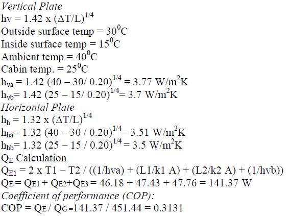
| Heat absorbed at evaporator, QE: |
| Dimensions of evaporator cabin=30x20x20cm3. Assuming laminar flow around all surfaces, we can use the following simplified equations for air: |
 |
FABRICATION AND ASSEMBLY OF THE SYSTEM |
| The parabolic dish collector was fabricated using eight iron bars of 48 cm length, 2.5 cm width and a large chromium plated aluminium sheet. The base was created by welding eight strips of curved steel to a central point at the base. Then a circular rim of steel of required diameter was created and welded each to the base. Two arms were welded to the dish for holding the heat source. Steel was used for the stand and a square base was used as a support. Mild steel sheet of length 70 cm and breadth 19 cm was taken and rolled into a cylinder to form the collector box.Two holes were made at the ends and fitted with a pipe extension for fixing 2.5 cm copper tubes. On the top on opposite points two small extensions were welded for fitting on the two arms of the dish. The vessel is fixed on the focal point of the parabolic dish. It is supported at the focal point with the help of cast iron bar. The vessel has a tilting mechanism so that vessel always remains straight.A mini domestic unit of Electrolux vapour absorption was used for the experiments. A vapour absorption system which had specifications and size similar to that of the mini fridge was used. Slight modifications were done to the vapour absorption system. |
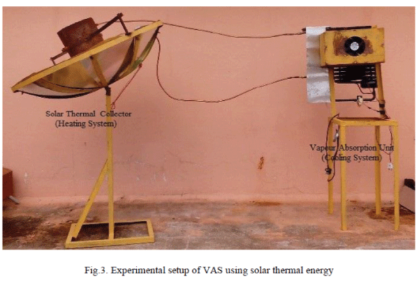 |
| An alternate pipe was provided to carry hot water through the generator from the solar thermal parabolic dish collector. This pipe was made up of copper with 4 cm in diameter and had an inlet for hot water and an outlet at the top for the colder water. This was placed such that it was in contact with the generator to ensure transfer of heat from the pipe to the generator tube. |
RESULTS &DISCUSSION |
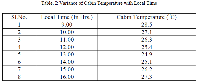
| After the total assembly and calculations were complete the setup was tested. The testing was performed from 9:00 am to 4:00 pm and the reading was noted. Every half an hour the parabolic dish was adjusted manually to track the movement of the sun. From the testing done it was noted that the lowest temperature achieved was 25°C. It was noted that the cabin temperature increased for a certain period and then dropped. The C.O.P of the system was obtained from the calculations as 0.3131. |
 |
| The result was noted that the collector fluid temperature increased with time but only up to a certain period. It can also be noted that the fluid temperature increases till 14:00 to a temperature of 120.3°C and then starts dropping.Now a second set of data is analyzed. Here cabin temperature variance is studied with respect to time. A digital thermometer was used for the purpose. It was noted that the cabin temperature reduces up to 13:00 hrs. and then starts to increase. The above pattern can be explained as there is a reduction in the solar radiation as evening approaches. |
 |
CONCLUSION |
| In this study the vapour absorption system using solar thermal energy was successfully fabricated. From the study it is observed that the results are up to the expected level and hence the same system can be the best method than the conventional systems.In future it is decided to compare the performance between conventional systems and vapour absorption system using solar thermal energy. |