ISSN ONLINE(2319-8753)PRINT(2347-6710)
ISSN ONLINE(2319-8753)PRINT(2347-6710)
Abdur Rahman1, Shabbir Ahmed R.M2, Dr. Mohamed Haneef3
|
| Related article at Pubmed, Scholar Google |
Visit for more related articles at International Journal of Innovative Research in Science, Engineering and Technology
Link Design plays important role in lifting machines. Links connected with pins will extend and contract during operation. So operation length is an important parameter in the design of Link mechanisms. Due to the advances in computer based Finite Element softwares, multi-body simulation provides good flexibility for the designer to choose better link mechanism satisfying. This type of simulation eliminates the need of prototype modelling and testing by which production cost will be less and design cycle time also reduces due to the flexibility of easier testing of number of mechanisms with in short time. In the present work, a single lever Grab tong is designed and analysed for structural strength. Initially theoretical calculations are carried out to check the minimum dimensions required for the problem. Later three dimensional cad modelling is carried out and structure is meshed with two dimensional and three dimensional elements. Design optimization is carried out to reduce the weight of the structure using computer simulation. Design optimizer a tool in ANSYS helps in fast optimization satisfying the functional requirements. Totally 26 sets are obtained which satisfy the functional requirements. The results are obtained for the best set also along with the graphical plots showing influence of design parameters on the structural weight of the single lever tong. Finally all the results are represented with necessary pictorial plots.
Keywords |
| Design optimization, Tool- Cad modelling, Hypermesh, ANSYS, Material- SAILMA350, Static behaviour |
INTRODUCTION |
| The Tongs has been used in the steel and iron industry for the last two centuries and by early civilizations as far back as the Roman Empire. Because of the tong’s simplicity, suitability for use in the worst mill duty environments, and long term reliability, the tong has a wide appeal to a large spectrum of users. Steel mills utilize tongs because they can be designed to withstand significant heat, are not affected by electromagnetic interference, have low maintenance requirements and can withstand significant shock loading. Service centres or fabricators like the fact that the tong requires few operators, and can be used at various locations around the plant without concern for electrical or special hook needs. The small end-users embrace the tong for its low cost, flexibility and durability. With minimum (or zero) down time on the process line a major goal of most organizations, the design characteristics of the tong grab make it an appropriate tool for many applications. |
| Although the lifting device is an important tool for many production line processes, the wrong application or improper use of a tong grab can cause significant property damage and even the loss of life. The core themes of this paper will be identifying the right tong grab for the application, describing the different design characteristics that should be employed, and maintaining the tong grab properly during the life of the device. This paper will concentrate on tongs that are activated by gravity (no motorization.) |
LITERATURE SURVEY |
| The lifting of a load requires a lifting appliance and a lifting accessory. A lifting accessory refers to a component or device that is not permanently fitted to the lifting appliance and that is used between the lifting appliance and the load, or fixed to the load to enable it to be lifted. Requirements concerning the structure of lifting accessories are presented in the Government Decision on the Safety of Machines (1314/1994, as amended) which came into force on 1 January 1995. The decision, hereinafter referred to as the Machinery Decision, applies to all lifting accessories taken into use and brought onto the market after 1 January 1995. The Machinery Decision requires manufacturers of lifting accessories, their authorized representative established in the European Economic Area or manufacturers that assemble lifting accessories from ready components to draw up a Declaration of Conformity for the lifting accessory and to affix CE marking to it. |
| Geometric analysis is closely associated with fixture planning and spatial reasoning. It determines the selection of the type and number of fixturing elements, support and locating elements, the order of datum planes, etc. The analysis also includes the checking of interference between work piece and fixturing elements, as well as cutting tools. Most of the early fixture research involved geometric analysis and synthesis of fixture construction with relatively little attention to kinematic and deformation analysis. Some of the earlier research works are briefly described. (Gandhi and Thompson, 1986) proposed a methodology for the automated design of modular fixtures. Some of the semi-automated systems were developed by (Jiang et al., 1988), (Grippoet al., 1987) and (Markus, 1988). (Nee and Senthilkumar, 1991) developed an automated fixture design system that integrates CAD with an expert system shell. Other systems using a 3-D solid modeller, an expert-system shell and a rule-based technique have been reported by (Lim and Knight, 1986), (Nnajiet al., 1988), (Nnaji and Lyu, 1990), and (Ngoiet al., 1990). These systems are capable of automatically generating partial or complete fixturing solutions for simple prismatic work pieces, based mostly on geometric analysis. Several of the above systems are based on modular fixtures. |
PROBLEM DEFINITION AND FINITE ELEMENT MODEL DEVELOPMENT |
3.1 PROBLEM DEFINITION: |
| Design, modelling and design optimization of a single lever Grab Tong used for lifting applications for structural safety is the main objective of the problem, which are as follows: |
| 1. Design calculations for links |
| 2. Design calculation of pins |
| 3. Overall modelling and meshing of the structure |
| 4. Analysis for structural safety |
| 5. Optimisation of the problem |
3.2 DIMENSIONAL REPRESENTATION OF THE PROBLEM: |
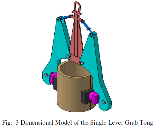 |
 |
3.4 MESHED MODEL |
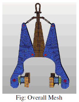 |
| The figure shows meshed geometry of the problem .Shell meshing is done along with brick meshing at the gripping or friction plates. Total of 8200 elements with 8590 nodes are used for maintaining connectivity. |
| Generally shell elements are best suitable for thin shell structures where width/thickness ratio greater than 10. Here mid surfaces are extracted and problem is solved in two dimensional domain by which meshing and solving difficulties will be reduced. Also accuracy of the problem is more as shell elements consider the twisting effects due to its higher degree of freedom(6) compared to 3 degree of freedom of solid elements. |
3.7 ASSUMPTIONS: |
| 1. The material is assumed to be isotropic and homogenous |
| 2. Analysis is done with in elastic limits |
| 3. Shell and plane elements are used for finding the solution |
| 4. The dent region is modeled by giving average thickness for each element |
| 5. All approximations applied to finite element solutions apply to this problem. |
RESULTS AND DISCUSSIONS |
4.1 RESULTS |
| The Single Lever Grab tong is analysed for structural optimization conditions. The analysis results are as follows. The following cases are analysed. |
| • Self weight analysis |
| • Design optimization results : |
CASE 1: SELF WEIGHT ANALYSIS RESULTS: |
| Since many structures fail by self weight. So initially the structure is analysed for self weight. The results are captured for displacement and stresses. The results are as follows. |
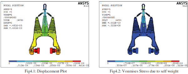 |
| The figure 4.1 shows displacement in the structure due to self weight. Maximum displacement value is around 0.000461m or 0.461mm. The red colour shows maximum deformation position. This is obvious as this work like a cantilever beam. |
| The figure4.2 shows stress developed due to self weight. Maximum stress is around 32.2Mpa as shown in the status bar. Maximum stresses are located at the support region and the central lever. |
CASE 2: INITIAL STRUCTURAL ANALYSIS: |
| Analysis has been carried out with a load of 200 tons acting on the friction plates is considered along with self weight. The results are as follows. |
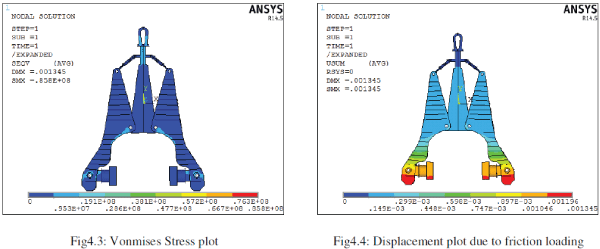 |
| The figure4.3 shows developed Vonmises stress due to loading. Maximum stress value is around 85.8Mpa. The stresses are located at the sharp geometrical variation regions. But the stress value is less than the allowable stress of the material. So the structure is safe for the given loading conditions. |
| The figure 4.4 shows developed displacement in the problem. The maximum displacement value is around 0.001345m or 1.345mm. Maximum deformation is represented by red colour. |
CASE 2 : DESIGN OPTIMISATION: |
| ANSYS parametric Design Languages helps in design optimization of the structures/machine. It requires definition of the design parameters in scalar quantity. Similarly, design optimizer uses state variables (Stress and deflection) as parameters of limiting the functional requirements. Finally it requires a objective function. This objective function generally weight of the structure. In the present structure, total of eight parameters are considered for design optimization. |
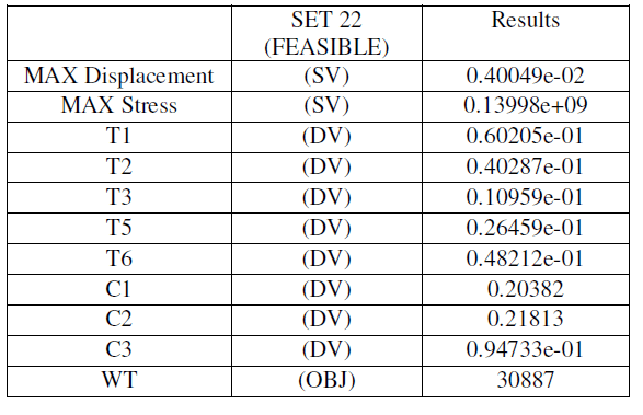
| The best set results for optimization is |
 |
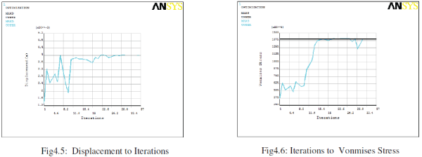 |
| The figure4.5 shows variation of displacement with iterations. The results shows displacement value is converging to the limiting value of 4mm. The sub problem iteration techniques has the algorithm to select the best set to obtain the required deformation with in short time. |
| The figure4.6 shows iterations to Vonmises stress. The Vonmises stress is converging to the required value after 15th iterations. All the final sets are almost converged to the stress value indicating lesser chances of weight reduction. |
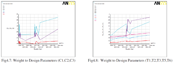 |
| The figure4.7 shows effect of design parameters on the weight of the structure. The graphs shows not much influence of parameter c3 on the weight formation. More effect can be observed from C1 parameter. This can be mainly attributed to higher initial value of C1 may help in reducing to the required dimension. |
| The figure4.8 shows influence of parameters T1,T2,T3,T5 and T6 on the weight reduction. The results shows greater influence of T1 and T2 on weight reduction or greater changes in the T1 and T2. Not much variation is observed in the T3, and T5. So the design optimizer helps in finding the influence of different design parameters with in short time. |
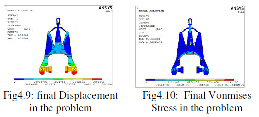 |
| The figure 4.9 shows displacement of 0.004 due to the optimized dimensions. Maximum deformation is observed at the bottom end and this deformation is the limiting deformation for the structure for proper gripping of the member to be lifted. |
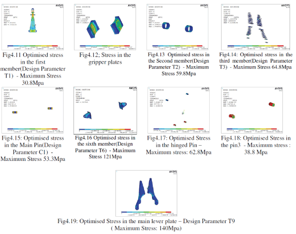
| The figure4.10 shows Vonmises stress in the single lever grab tong. Maximum stress is around 140Mpa which shows converged results for the problem. Maximum stresses are observed at the pin regions due to stress concentration. This can be further reduced by using washer type arrangements. |
| The stresses in the optimized components are shown below. |
 |
4.2 DISCUSSION |
| Grab tongs are very common in engineering applications. Grab tongs vary from single level (Scissor) to multilevel depending upon the mechanical advantage and height to be lifted. In the present work, few members are theoretically checked for design safety. Later the whole assembly is built and meshed with shell and solid elements. The elements are grouped to 9 collectors, each representing one thickness which can be easily optimized by specifying the required state parameters like stress , deflection etc. In the present, ANSYS parametric design language based designer optimizer code is used to get a total of 37 sets for which the thickness required for the geometry will be obtained from the system. 22nd iteration is chosen as the best set satisfying the functional requirements i.e., satisfying the displacement limits and stress limits. Great reduction of weight is observed by this sub problem approximation technique. Vonmises stress is the limiting theory for ductile materials, as most of the failure of ductile structures match with Vonmises theory. The limiting deflection is set based on IS codes for structural deformation. |
CONCLUSION AND FEATURE SCOPE |
5.1 CONCLUSION |
| A Single Lever Grab Tong is cad modelled and checked for minimum sections and design optimization is carried out using Finite element software ANSYS. The overall summary is as follows. |
| Initially Geometry is built using Catia, a modelling software for the given dimensions. The model is imported to Hypermesh for good quality mesh and shell and solid mesh are appropriately. Collectors are created to group the members for further optimization. The pins are represented by beam elements and through RBE3 element connections are given between pin and shell geometry. This present problem is having higher self weight, due to which self weight analysis is done. The results shows both developed stress and deformation are within the allowable range for the material. Further with the external gripping load, the analysis is carried out and results are presented for assembly and for individual components. The results shows both deformation and stress are with in the allowable range of working. Also it is observed that many components stresses are less and so optimization can be carried out. A design optimizer based on Ansys parametric design language is a good tool with ANSYS for optimising the geometries. Totally 8 design parameters (T1,T2,T3,T5,T6, C1,C2 and C3) are considered along with 2 state parameters(deflection and stress) with weight as the objective function. Sub problem approximation technique is used for design optimisation setting 50 possible sets. But the results are converged for 37 sets and a best design set is obtained as set number 22. Even the weight is reduced from initial 47596kgs to 30887kgs. Almost a reduction of 16709 kg which is very critical in cost of the grab tong. Almost a reduction of 35% can be observed. The graphical variations shows greater influence of T1,T2 and C1 parameters on the weight. Final results shows obtained values are with in the allowed range of the material. All the results are represented with necessary pictorial plots. |
5.2 FURTHER SCOPE |
| • Analysis can be further done by composite material usage |
| • A dynamic effect on lifting can be analysed. |
| • Topology optimization can be carried out. |
| • Further analysis can be extended to reduce the normal load on the gripper plate by increasing the friction. |
| • Possible thermal effects can be considered |
| • Further change of effect of Centre of gravity effect can be considered |
ACKNOWLEDGEMENT |
| I would like to express my sincere gratitude to my Parents, Young and dynamic Principal, Beloved Head of the Department and my energetic Guide, without their support and prayers it would not have been possible to complete this project. Last but not the least, I would like to extend my thanks to my friends who provided me with valuable suggestion to improve my project. |
References |
|