International Journal of Innovative Research in Science, Engineering and Technology
ISSN ONLINE(2319-8753)PRINT(2347-6710)
ISSN ONLINE(2319-8753)PRINT(2347-6710)
M. J. Madu1>, I. S. Aji2, B. Martins3
|
| Related article at Pubmed, Scholar Google |
Visit for more related articles at International Journal of Innovative Research in Science, Engineering and Technology
An admixture burner for the atomization and combustion of used engine oil and kerosene for foundry application was constructed and tested to reduce the cost of operation in the foundry since the fuel is easily accessible, in addition to avoid pollution by the incessant dumping of the used engine oil. The nozzle, springs, screws, tank and the fuel hose were predominantly used materials for its construction. A test was carried out to determine the time taken for some selected engineering materials (copper, aluminum, brass, and lead) to melt using the admixture burner with an appropriate combination ratio of 1:5 for kerosene and used engine oil and the ratio of 15:1 for air and fuel respectively, which was considered to be the most reactive, because it ignites easily compared to other ratios. The time taken for 1kg of each selected engineering materials to melt were 49, 15, 22 and 7 minutes for copper, aluminum, brass and lead respectively. The burner has a thermal efficiency of 66%. Experiment also showed that that the density of the admixture, decreases with an increase in the temperature making it easy to mix and ignite for combustion.
Keywords |
| Admixture, Atomization, Combustion, Engine Oil, Foundry. |
INTRODUCTION |
| Fuel burning devices are devices that produce heat (thermal energy), derived from burning fuel and required for technological processes especially in the industry [1]. There are so many types of burners with different fuel types. Examples of such fuel are the biodiesel, ethanol, vegetable oil etc. Burning devices that make use of this fuel are classified as the oil burners, liquid fuel burners, and the combined gas liquid fuel burners. Apart from its classification by the type of fuel used, a burner can also be designed based on factors like the combustion chamber geometry, type of oxidizer and also heat transfer requirements which include flame temperature and heat distribution etc. Typical examples of burners which are developed based on the type of oxidizer are the oxy-fuel burner and air fuel burner [2]. Various works relating to the construction and testing of burners were studied, they include: Development of a high velocity burner for furnace operation. The main components of this burning device are the burner nozzle, mixing tube, downstream section and a cross-connected regulator for air fuel ratio control. It employs forced draft in mixing the fuel and air [3]. Design, Construction and Performance Evaluation of a Biogas Burner, the work was geared towards modification and improvement of the burner and its efficiency [4]. Porous Radiant Burners which make use of liquid petroleum gas were also developed and tested for cooking applications [5]. Other authors studied the Design and Construction of Atmospheric Gas Burners where they dwelt most on the theory of flow of gas through different types of orifice [6]. |
| In University of Maiduguri’s Faculty of Arts, burners of different types have been constructed for use in the kiln for firing or drying of things such as the bricks. A typical example is a burner that uses kerosene only as its fuel. The burner is made up of the nozzle, manual pump, hose and the fuel tank. The pressure required for ignition is supplied by the manual pump which is fixed at a small opening on the fuel tank. Kerosene then passes through the nozzle as it comes in contact with heat supplied by the rings in the kiln. This type of burner is classified as a liquid fuel burner. |
| Similarly, a burner that uses only used or waste engine oil has its fuel tank located at a certain height and uses electricity which powers the electric motor and helps rotate the blower which supplies the air required for combustion as the used engine oil flows through the burner. Despite the presence of the few types of burner, they are not constructed for carrying out foundry applications. Also, considering the availability of used engine oil, there stems the need to construct an admixture burner for the purpose of carrying out foundry operations. Aji et al. [7] presented a work on the admixture of used engine oil and kerosene as a substitute for industrial fuel. Various rations of the mixture were used with an optimum combination of engine oil and kerosene as 6:1 with four liters of the mixture melting 10kg of zinc in 22 minutes. The result concluded that kerosene and used engine oil can be used in foundry workshop for firing furnace effectively. Aji et al. [8] earlier research focused on the prospect of some selected vegetable oil as an additive to motor fuel. It described the improvement in the performance and quality of motor fuel with respect to its existing property. Groundnut oil, palm oil, Shea butter, beniseed oil and African bush mango were used as a source of anti oxidant additives. The α- tocopherol obtained from the vegetable oil served as the best substitute to the existing synthesized antioxidant additives being used. This paper therefore presents the result of the design, construction and test of an-admixture burner that uses usedengine oil mixed with kerosene for foundry applications as an alternative to electric burners. |
MATERIALS AND METHOD |
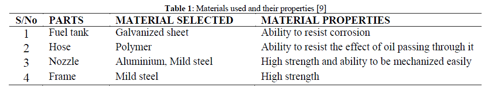
| The selection of material to be used for the different component in this design involves the following consideration: Cost and availability of the material, material property - Mechanical, physical and chemical properties (its ability to resist corrosion due to prolonged usage. The best selection of materials could be made after considering factors such as ease of fabrication, corrosion resistance and its economic cost or consideration. Such of the important design criteria to be made include: high strength, stiffness, rigidity etc. the table below describe the selection of each component. |
 |
| The following design considerations were considered during the process of constructing a burner for foundry operation: Availability and the use of local components and material, simplicity of design, economic consideration and the use of simple instrument and tools [10]. The tools used during the construction include: hacksaw, vernier calliper, measuring tape and the machine use are the welding machines, lathe machine, and drilling machine. Operations that were carried out include – cutting, welding, drilling, spraying etc. |
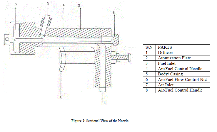
| Nozzle |
| The nozzle is a device that increases the velocity of a fluid at the expense of pressure, it is located at the tip of the spray gun and it transmits fluid. |
| Spray Gun Nozzle Head |
| A spray gun nozzle head atomize liquid using pressurized gas. The nozzle head include a central nozzle having an orifice for supplying the liquid to be atomized. A cap having a funnel shaped chamber is mounted over the nozzle to define an annular passage for supplying the pressurized gas (air). The cap as an orifice is aligned with the nozzle orifice such that the nozzle orifice is recessed upstream from the cap orifice to define a region adjacent to the nozzle orifice in which the liquid atomize by the pressurized gas into a liquid prior to being expelled through the cap orifice. The spray gun is provided with valves, used for controlling the flow of fluid and allow for easy dismantling, cleaning and other maintenance work. |
| The Spray Gun |
| The spray gun is fitted with a nozzle head, it is also provided with handle grip to which a supply of pressurized gas such as air is connected at the inlet. Pressurized air travels through the handle passage. A substantial portion of the air flows around the fluid block in the central passage to the nozzle head for the atomization of used engine oil. The engine oil is connected to a threaded inlet by a suitable coupling. |
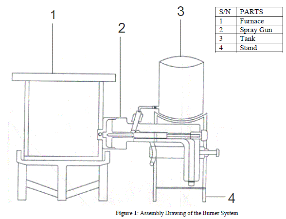
| Assembly and Principle of Operation of the Burner |
| The different part of the burner were assembled together in the following order: the air inlet adapter was bolted to the handle grip (main body), the valve was inserted into the hole provided in the handle grip, while flow adjustment screw was bolted to the handle grip such that after fixing, it can be adjusted base on the viscosity or density of the fluid to be used. The atomizing plate was placed between the handle grip (at the spray end) and atomizing plate cover. The atomizing plate was then screwed to the handle grip (main body), and finally, the fuel hose was connected to the fluid blockhouse pipe. The burning device uses the principle of combustion in which air is required or supplied to enhance burning. The selected engineering material to be melted are placed in a furnace and connected to the burner. As it burns, each metal melt at different temperature, in a given amount of time. The nozzle of the burner increases the velocity of fluid; the fuel tank stores the admixture of used engine oil and kerosene and the threaded portion to enhance smooth burning which generate heat energy required for melting. |
 |
 |
EXPERIMENT |
| The construction of an admixture burner that uses used engine oil as a replacement for conventional fuel (petrol and diesel) in the workshop to reduce the running cost of operation in the foundry workshop and also to reduce the effects of pollution caused by incessant disposal of used engine oil in the environment was done. The burning device is a setup that makes use of the principle of combustion in which a certain ratio of air to fuel is required for burning to take place. The major parts that make up the burner include the nozzle, spray gun head, air source, tank, hose and frame with each having its function. After assembly, air from the source is required to support the burning process which produces thermal energy required for melting the selected metals. This construction results in providing an alternative for the foundry workshop by reducing the cost of fuel used and also reduce the effects of pollution caused by this used engine oil especially when it is not properly disposed. The admixture burner is solely limited to foundry operations involving melting of metals. |
DESIGN ANALYSIS |
| The most important characteristics of the machine are its productivity, maintenance cost, ease of operation and an attractive finish. The priority of each characteristic depends on the purpose of the machine. Economic consideration is of great importance in engineering. This is achieved by increasing the service life and reducing the cost of operation. |
| Time required emptying the fuel reservoir |
| The tank contains a certain amount of fluid, which will flow at a certain flow rate. The volume and the discharge of the fluid is analyzed using the following relations- |
| Tank |
| Rajput [11] define Volume flow rate as |
| Q= AV………………………………........................ 3.1 |
| Where V = volume of tank, A = Area and Q = Discharge |
| Separation losses in pipe flow |
| Loses which occur as a result of various pipes fitting such as bends, valves and also sudden enlargement and contraction of the pipe |
| For losses due to friction, using Darcy equation, |
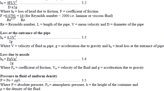 |
| The speed of fluid flow can vary along paths of the fluid. The pressure can also vary, depending on the height as in the static situation and it also depends on the spread of flow. From continuity equation, |
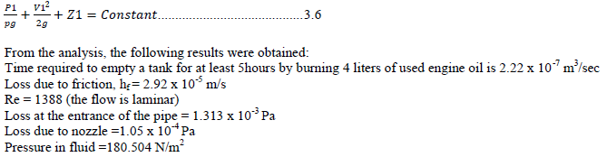 |
| Air Fuel Ratio |
| Using 84% of used engine oil and 16% of kerosene by mass. |
| The mass of air required for combustion of the burner is calculated below: |
| Oxygen required to burn 1kg of used engine oil = 2.66kg |
| Oxygen required to burn 0.84kg of used engine = 0.84 x 2.66kg |
| Oxygen required to burn 1kg of kerosene = 8kg |
| Oxygen required to burn 0.16kg of kerosene= 0.16 x 8kg |
| Oxygen required= (0.84 x 2.66) + (0.16 x 8) kg |
| Air required = ((0.84 x 2.66) + (0.16 x 8)) 4.35 kg = (2.23+1.28) 4.35 kg = 15.268 kg |
| The air to fuel ratio by mass is 15.268 to 1 |
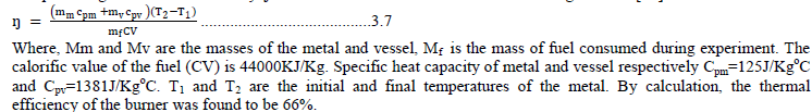
| Thermal Efficiency of the Burner |
| The percentage of thermal efficiency Ãâ¦Ãâ¹ of burner is estimated based on the following formula [12]. |
 |
DISCUSSION |
| A test was carried out using some selected materials and the result obtained was compared to that of a blacksmith. The admixture burner saves time and more of the quantities of the selected materials are melted. It was during the experiment that the time taken by the blacksmith furnace to melt a particular metal is more than the time taken by the use of an admixture burner. Table 2 show the different result obtained while testing the burning device. |
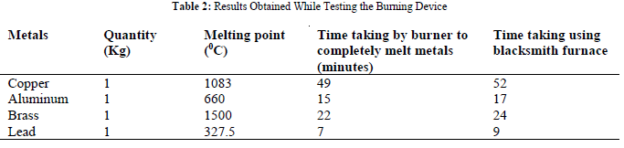 |
| At 1083 oC, one kilogram of copper melted in 49 minutes, one kilogram of aluminum melted at 15 minutes at a temperature of 660 oC. Similarly, at 1500 oC brass of one kilogram melted in 22 minutes and lead melted in 7 minutes at 327.5 oC. The temperatures attained by the burner shows that it can be used for higher temperature furnace applications such as metal heat treatment and reheating etc. |
| Similarly, the cost and quantity of fuel required by an admixture burner is less than the cost of charcoal used by the blacksmith to supply thermal energy. When ignited, the burner generates heat and continuously produces the thermal energy required for foundry application. While the blacksmith burner requires more energy for the production of heat as the blower is manually operated. Experiment has also shown that the density of the admixture decreases with increase in temperature there by making it easy to mix and ignite. In view of this, the burner can be use in the student workshop and for foundry application since it consume lesser amount of fuel and time. |
CONCLUSION |
| An admixture burner using kerosene with used engine has been found to replace the conventional fuel in the workshop thereby reducing the cost of operation in the foundry operation. The designed burner has been made simple so that it could be understood and operated even by unskilled persons. Most of the materials used for the construction are locally available and affordable making the burning device easy to produce and maintain. The design construction and testing of the admixture burner can be improved by making provision for a better process of purifying the fuel. |
References |
|