ISSN ONLINE(2319-8753)PRINT(2347-6710)
ISSN ONLINE(2319-8753)PRINT(2347-6710)
A.Muniappan1, C.Thiagarajan2, Taukir Azam3, X.Joseph Raj4
|
| Related article at Pubmed, Scholar Google |
Visit for more related articles at International Journal of Innovative Research in Science, Engineering and Technology
Radiators are used to transfer thermal energy from one medium to another for the purpose of cooling and heating. In this work an attempt is made to find out the coupled temp-displacement analysis of a radiator tube element at 615°C in operating condition of a Brazing process to prevent the leakage, which is the major problem facing in the heat exchanger at header and tube joints. A coupled temp-displacement analysis is carried out to find out the temperature, heat flux, stress strain and thermal expansion of radiator tubes (consider 10 different tube dimensions). And based on the expansion of the tubes suggesting the perfect tube expander tool which is used to expands the tube and helps out the preventing the leakage which is occurring at header & tube joint. Present study uses the coupled temp-displacement analysis tool ABAQUS/CAE edition 6.10-2 to perform an expansion study on a radiator tubes.
Keywords |
| Heat Exchanger, Radiator, Abacus/CAE, Temperature–displacement analysis. |
INTRODUCTION |
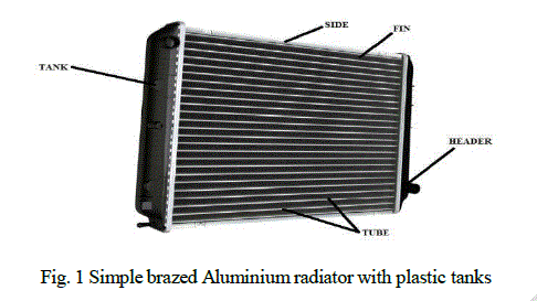
| Radiators are heat exchangers used to transfer thermal energy from one medium to another for the purpose of cooling. Radiators are used for cooling internal combustion engines, mainly in automobiles but also in pistonengine aircraft, railway locomotives, motorcycles, stationary generating plant. The radiator transfers the heat from the fluid inside to the air outside, thereby cooling the fluid, which in turn cools the engine. Figure 1 shows a typical radiator used in automobile. Radiators are also often used to cool automatic transmission fluids, air conditioner refrigerant, intake air, and sometimes to cool motor oil or power steering fluid. Radiators are typically mounted in a position where they receive airflow from the forward movement of the vehicle, such as behind a front grill. This coolant is usually water-based, with the addition of glycols to prevent freezing and other additives to limit corrosion, erosion and cavitation. However, the coolant may also be oil. The first engines used thermo siphons to circulates the coolant; today, however, all but the smallest engines use pumps. As it circulates through the tubes, the coolant transfers its heat to the tubes which, in turn, transfer the heat to the fins that are lodged between each row of tubes. The fins then release the heat to the ambient air. Fins are used to greatly increase the contact surface of the tubes to the air, thus increasing the exchange efficiency |
 |
MATERIALS & METHOD |
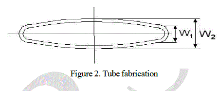
| Several types of brass tubes can be used to manufacture Cupro Braze heat exchangers. These tubes are uniformly made from strip because thin gauges are required for lightness and efficient heat exchange. Tube fabrication requires that the edges of the strip are reliably bonded together. The tube seams can be sealed during the brazing process or they can be welded prior to the brazing process.Tubes for use in the Cupro Braze process should be specified with a crown that is higher compared to the crowns of tubes for use in a soldering process. The crown should be 0.4mm to 0.8mm for tube widths 12mm to 25mm. A higher crown results in a more consistent bond between tube and fin. |
 |
| CONTROLLED ATMOSPHERE BRAZING |
| Aluminum radiator cores are brazed in a furnace to join the tubes, fin, and headers. This brazing process is commonly referred to as CAB (Controlled Atmosphere Brazing) for the name of the flux used in the process. |
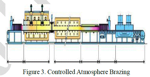 |
| A typical CAB furnace is made up of multiple sections that are bol ted to ge the r to create a large single system. This assembly can measure 75-150 feet long and cost as much as one million dollars. Aluminum radiator cores are brazed in a furnace to join the tubes, fin, and headers. This brazing process is commonly referred to as CAB (Controlled Atmosphere Brazing) for the name of the flux used in the process. Priority to brazing the cores must be cleaned and fluxed. The most common way to apply the flux is to mix the flux with water and spray it onto the core. A flux machine typically has multiple zones including a spray application zone, air blower zone, and dryer section. The flux machine must be fabricated with stainless steel material to prevent rusting. A conveyor belt mechanism is use to transfer the part through the three zones and out to the dehydration oven. A separate tank with an agitation motor is used to keep the water/flux slurry mixed. Special diaphragm pumps are used to transfer the mixture. |
| Certain areas of the core require more flux than others but most companies will simply apply the same amount everywhere because it’s easier. We choose to do it the hard way because the end result is clearly better. The photo (right) shows a 15% flux/water mixture is sprayed onto the core, flooding the tube and fin section. This insures that 100% of the internal components are coated with flux but in a lower percentage to minimize excess flux build up and fin clogging. Following the machine fluxing, the cores are removed and a second application is applied to the tube and header area. This is the most critical area of the core and a higher (30%) concentration of flux/alcohol is used. |
| FURNACE BRAZING |
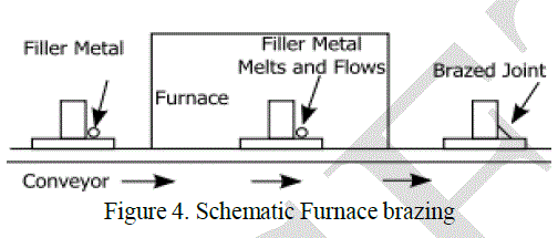 |
| Furnace brazing is a semi-automatic process used widely in industrial brazing operations due to its adaptability to mass production and use of unskilled labor. There are many advantages of furnace brazing over other heating methods that make it ideal for mass production. One main advantage is the ease with which it can produce large numbers of small parts that are easily jigged or self-locating. The process also offers the benefits of a controlled heat cycle and no need for post braze cleaning. Common atmospheres used include: inert, reducing or vacuum atmospheres all of which protect the part from oxidation. Some other advantages include: low unit cost when used in mass production, close temperature control, and the ability to braze multiple joints at once. Furnaces are typically heated using either electric, gas or oil depending on the type of furnace and application. However, some of the disadvantages of this method include: high capital equipment cost, more difficult design considerations and high power consumption |
TUBE MANUFACTURING |
| TUBE FORMING |
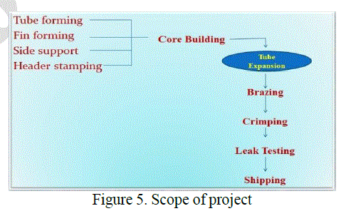
| Tube forming is the process of forming the flat sheet metals into rectangular cross sectioned tubes, this tube forming will be performed in tube mill machine. The flat sheet continuously feeds in between the rollers and converted into round tubes, than this round tool is further forms into the rectangular cross section tubes. The sheet metal ends welded by SIM welding process. After forming they will cut into the required length |
 |
| FIN FORMING |
| It is the process where radiator fin is bent in the form of continued rectangles to form a hollow grille with multiple segments. The bottom segment of the radiator fin is milled into a slot, which is fit into the base board. The middle of the base of the said radiator fin is fit perfectly into the trench on the base board. By dint of shrinkage occurred during the sintering operation of the base board, and becomes an integral part of the base board. |
| SIDE SUPPORT |
| Side support is manufactured by using press tools which the flat sheet metals continuously feed into the press tool. And they will be forms into required shape. |
| HEADRER STAMPING |
| According to a preferred embodiment the header is formed in a single sheet of metal by an inexpensive stamping operation and turned upon itself, whereby there is afforded a pair of plate portions for face to face sealed engagement, one having a series of flanged openings or tubular formations for nested assembly with the passages or tubes of the heat transfer unit and the other having cooperating raised ribs to constitute branches or ducts communicating with 1B an enlarged chamber at the fold or bight of the sheet joining adjacent edges of the plate portions. Working the sheet to shape and the formations produced impart strength thereto so that relatively low cost, light gage sheet material may be employed even for pressure system installations. |
| CORE BUILDING |
| A “core” is really the sum of a group of parts. This includes the headers which is a multi- slotted plate that all the tube ends are brazed into. The stack up of tubes, fin, and side channels make up the remainder of the core. It is the core and the core alone that dictates the effectiveness of the radiator in which it is used. Aluminum radiator cores are brazed in a furnace to join the tubes, fin, and headers. This brazing process is commonly referred to as CAB (Controlled Atmosphere Brazing) for the name of the flux used in the process. |
| TUBE EXPANSION |
| The tube expansion machine is used to expand the ends of tubes after the header cores and tubes are assembled. And its help out to make perfect gap which required for brazing operation between tubes and header joint. There are many types of tube expanding machines are available. Example Hydraulic expansion machine, Mechanical expansion machine etc. In this tube expansion process the expanding tools are inserted into the tubes by hydraulically & makes the tubes into the perfect required size and helps out to preventing the leakage cause between header joint and tube. |
| BRAZING |
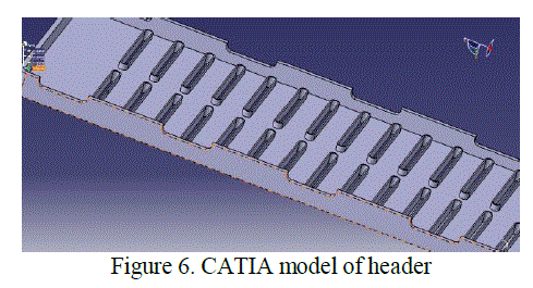
| Brazing is a metal-joining process whereby a filler metal is heated above melting point and distributed between two or more close- fitting parts by capillary action. The filler metal is brought slightly above its melting (liquids) temperature while protected by a suitable atmosphere, usually a flux. It then flows over the base metal (known as wetting) and is then cooled to join the work pieces together. It is similar to soldering, except the temperatures used to melt the filler metal are higher. The perfect brazing gap for header joints and tubes was 0.03 to 0.08 mm. Figure 6 shows CATIA model of the header. |
 |
| LEAK TESTING |
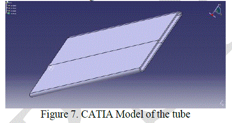
| Leak test will be done to check out weather the radiator is getting any leakage, at any tube and header joint. If any leakage is not showing and the pressure is showing 1.0 bar than the radiator is marked as ok. If the pressure is showing above 1.0 bar or 1.1 bar than the leak testing machine shows to be leak observed and they were sending for re brazing operation. Bypass time using for leak testing 50sec. It is recommended to check the tube-fin joints for the first samples when something in the production has been changed. The check should be repeated until the right quality has been reached. Figure 7 shows CATIA design model of the tube. |
 |
BRIEF DESCRIPTION OF DESIGN & ANALYSIS |
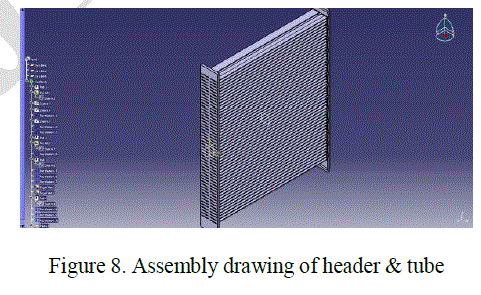
| In this project we are concentrating on the leakage occurring between radiator header and tube joint. If the gap between the header and tube joint was perfectly made than there won’t be any leakage between header and tube. The perfect gap required between header and tube is 0.03mm to 0.08. This is the good brazing gap required. If the gap is 0.03 to 0.08mm between the header and tube joint will get the perfect brazed together. And in this design part, we have made 2D& 3D models of radiator header and tube individually. And we made header tube assembly also by using the software CATIA V5. Figure 8 shows assembly drawing of header & tube. |
 |
| PROPERTIES |
| For doing this analysis we chosen the properties of A3003 material are listed below: |
| Thermal conductivity = 237 w/mk |
| Density = 2700 kg/m3 |
| Poisons ratio = 0.35 |
| Co efficient of thermal expansion = 0.000025 μ/mk |
| In this analysis process we are finding expansion of the based on the temperature variation from 30°c to 615° c. That’s why we selected the step module coupled temp- displacement study state. Which helps out to find the expansion of the tube based on the temperature varies from 30°c to 615° c. In mesh module we given the meshing global size is 4.28mm. And the element type is used C3D8T (An 8-node thermally coupled brick, trilinear displacement and temperature).In visualization module is used to see the result, as well as we can find out the deflection ranges from minimum to maximum based on the input given. And the green colour indicates the minimum deflection & red colour indicates the maximum deflection of the module. By view tools we can check out whatever the view we need. |
PERFECT TOOL DESIGN |
| The tube expansion tool is used to expand the ends of tubes after the header cores and tubes are assembled. And its help out to make perfect gap which required for brazing operation between tubes and header joint. The good brazing gap is 0.025 to 0.08 mm. this gap is maintained by using perfect expanding tool. The expanding tool should not damage the tube cross section, it should only expand tube into the perfect required size. By analyzing the tube cross section with 10 different iterations we got the perfect tube size is 1.89 to 1.91mm. Co efficient of thermal expansion = 0.000025 μ/m k In this analysis process we are finding expansion based on the temperature variation from 30°c to 615° c. That’s why we selected the step module coupled temp- displacement study state. Which helps out to find the expansion of the tube based on the temperature varies from 30°c to 615° c. In mesh module we given the meshing global size is 4.28mm. And the element type is used C3D8T (An 8-node thermally coupled brick, trilinear displacement and temperature). In visualization module is used to see the result, as well as we can find out the deflection ranges from minimum to maximum based on the But if we make the tube sizes between these ranges during the inserting process tubes into the radiator header slot we need to face so much difficulty while inserting. And its causes more time while inserting tubes into the header joint due to the less gap between header slot and tubes. |
| In the case the tool should help out to make the tube into this perfect size (1.89 to 1.91mm) from the initial dimension which won’t makes time delay and difficulty during the inserting tubes into the header slot. If the initial dimension (like 1.83 to 1.86mm) was small when compared to the header slot dimension then the inserting process easy and faster. Considering all this points we designed the tool which can be expands the tube from 1.83mm to the perfect required tube size (1.89 to 1.91mm). This perfect tube dimension forms good joint with header slot when the tolerances are minimum (1.97mm) or maximum (2.07mm). |
RESULT & DISCUSSION |
| Based on the 10 different dimensions thermal expansion we found out the perfect tube size which makes perfect joint with the header slot. The analyzed tolerance results were listed below: |
| Dimension 1.83 mm |
| When we consider the minimum tolerance (1.97mm) of the header slot dimension, then the gap/ side coming 0.06mm, and this is the good brazing gap/side for the particular material (A3003). When we consider the maximum tolerance (2.07mm) of the header slot dimension, then the gap/ side coming 0.11 mm, and this gap was beyond the good brazing gap/side for the particular material (A3003). |
| Dimension 1.90 mm |
| When we consider the minimum tolerance (1.97mm) of the header slot dimension, then the gap/ side coming 0.025mm, and this is the good brazing gap/side for the particular material (A3003). |
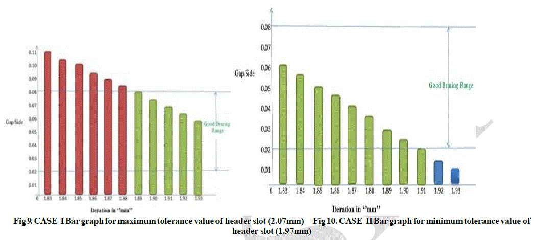 |
| From figure 9& 10, c a s e -I & case-II bar graph, the dimensions which are there in green colour in both the cases, the dimensions are considered the perfect tube size. i.e. 1.89, 1.90, 1.91mm. And 1.92 & 1.93mm dimensions are the acceptable tube size. |
CONCLUSION |
| There are many problems facing in the radiator assembly line. In that one of the major problems was leakage occurring at the header tube joint. This leakage was occurring because of improper brazing done in between the joint of header and tube. And also the Controlled Atmospheric Brazing (CAB) was going on at 615°c. At this 615°c temperature we analyzed the tube expansion which the thickness of the tube is 0.406mm. Taking the external diameter of the tube 1.83 to 1.93mm, 10 different iterations were analyzed. For this analysis we consider the header slot expansion was negligible, because the thickness of the header slot was 2mm. Based on the expansion of the tube (based on analyzing result) at 615°c and considering perfect brazing gap from 0.03 to 0.08mm between the header and tube joint we designed a expansion tool. This tool will helps out to do expansion of the tube to required perfect size which keeps gap between the headers and slot 0.03 to 0.08mm. And this tool will helps out keep the perfect gap between header slot and tube when the header slot dimensions were minimum tolerance or maximum tolerance. |
References |
|