This paper proposes a unified power flow controller (UPFC)-based oscillation damping controller for use with a permanent magnet synchronous generator (PMSG)-based offshore wave farm (OWF). A novel intelligent damping controller (NIDC) was used to increase the stability of power control and improve the performance, where the proposed NIDC consists of the adaptive critic network, the Functional Link based Elman Neural Network (FLENN), and PID linear damping controller. The UPFC is used with the NIDC to OWF, which is connected to a single-machine infinite-bus to improve system stability. The PID damping controller is analysis of complex eigenvalues based on a theory of modal control. The node connecting weights of the FLENN and critic network are trained online. The proposed NIDC can be used to achieve better damping characteristics. The internal power fluctuations in the power system can also be effectively alleviated under variable wind power generation
Keywords |
| unified power flow controller (UPFC), Functional Link based Elman Neural Network (FLENN),
offshore wave farm (OWF), PM synchronous generators (PMSG) |
INTRODUCTION |
| Wind energy systems are attracting considerable attention as clean and safe sources of renewable power. Among the
types of generator used for wind turbines, technical developments have moved from fixed-speed to variable-speed
designs [1]. In recent years some small-scale offshore wind farms (OWFs) have been evaluated, while a number of
large-scale OWFs have been constructed and are now in commercial operation. Researchers have examined induction
generators with wound-rotor or cage-type rotors [2], [3], but in recent years there has been increasing interest in
Permanent Magnet Synchronous Generators (PMSG). Such generators are attractive due to their compact structure,
high air–gap flux density, high power density, high torque-to-inertia ratio, and high torque capability [4]. When OWFs
deliver a large amount of electric power to power grids, the inherent power fluctuations that occur can have adverse
impacts on the power quality of the systems to which they are connected. This paper thus proposes the use of a unified
power flow controller (UPFC) in order to reduce the power fluctuations of large-scale grid-connected wind farms. |
| The UPFC proposed by Dr. Gyugyiin 1991, is the most flexible and powerful Flexible AC Transmission Systems
(FACTS) device [5]-[8], which can provide an effective means to control the power flow, voltage and damping, and
thus improve the transient stability of a power network. In the control of a UPFC series branch, both the active and
reactive power flows in the transmission line are influenced through the series injected voltage as well as its phase
angle [7], [8]. A fixed-parameter controller with classical control may thus not be effective for a UPFC [8], [9]. In such
cases a flexible controller may be required, such as one based on neural networks [6], PSO [10] and robust control
methodologies [11], in order to cope with system uncertainties and enhance the damping performance of a UPFC. |
| The Elman neural network (ENN) is a partially recurrent network model that was first proposed in 1990 [12]. The
ENN is better than a static feed-forward network, and thus is widely applied with dynamic systems, although its
convergence and training speed are usually very slow, and this it is not suitable for complex systems. In order to
improve the ability to identify complex dynamic systems, a functional-link neural network (FLNN) is adopted in this
paper to improve the performance of the ENN. This improved performance is because the input variables are linearly
independent trigonometric basis functions which are used for a functional expansion of the FLNN in the extended
space for classification. Moreover, the FLNN can capture the nonlinearly input–output relationships among a suitable set of polynomial inputs, since the high-order effects are incorporated in the input variables into higher dimensions of
the input space. The FLNN can thus effectively approximate a nonlinear function [13], and so it is suitable to be
applied in complex power system applications, such as the one examined in this work. |
| This paper proposed the design of a novel intelligent damping controller (NIDC) consists of a PID linear controller,
functional link-based Elman Neural Network (FLENN) and critic network for a UPFC damping controller. The PID
linear controller is analysis of complex eigenvalues based on a theory of modal control. An FLENN is unlike
conventional controllers, the performances of which degrade for such changes and require retuning to produce the
desired performance. The integrated OWF with a synchronous generators (SG) system is studied under the conditions
of changes in wind speed, a three-phase short circuit fault and the transient responses. An NIDC is proposed in this
work to achieve simultaneous power flow control and stability improvement. |
ANALYSIS OF SYSTEM MODELS |
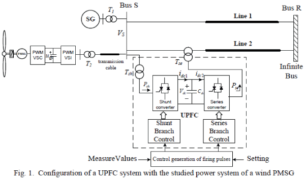
| Fig. 1 shows the configuration of the system studied in this paper. The OWF represented by a large equivalent
aggregated PMSG is driven by an equivalent aggregated wind turbine through the gearbox in [2]. The SG with a
capacity of 555MVA is connected to a single-machine infinite-bus (SMIB) through a transformer T1 and two parallel
transmission lines: Line 1 and Line 2. Line 2 contains the proposed UPFC located near Bus S. The aggregated OWF
containing 200MW PMSG-based wind turbine generators is connected to Bus S through a T2 transformer and a 15 km
transmission cable. The equivalent wind PMSG is driven by an equivalent wind turbine through an equivalent gearbox.
The employed capacity of the proposed UPFC is 160 MVA, and its series voltage is added to Bus S voltage VS by the
series connected transformer Tse. The shunt converter of the UPFC connected in shunt with the AC power system via a
shunt transformer Tsh is primarily used to provide the real power demand of the series converter at the common DC link. |
| A. Wind Turbine Characteristics |
| The wind turbine input is the variable wind and the output is the mechanical power turning the generator rotor blades
[4], [15].The output mechanical power available from a wind turbine can be obtained by |
 |
 |
 |
| where Cp1 to Cp9 are the wind turbine constant coefficients of Cp |
| B. PMSG |
| The wind generator chosen for this study is a three-phase PMSG, where the mechanical torque (Tm), electrical torque
(Te) and dynamic equation can be found in [4]. The machine model of a PMSG can be described in the rotor rotating
reference frame as follows [4] |
 |
| and |
 |
 |
| The configuration of a field-oriented PMSG system consists of PMSG, a current-controlled PWM voltage source
converter (VSC) and; vnverter (VSI), a field-orientation mechanism, including the coordinate translator, and a speed
control loop. The input and output d, q axis voltages of VSC and VSI of wind PMSG could be expressed as |
 |
 |
 |
| C. Modeling of the UPFC |
 |
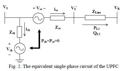
| Under the synchronous reference frame, the d-q axis components of the series and shunt controllers are used to
generate the direct and quadrature components of the modulated voltages. The direct and quadrature components of the
voltages are then used to generate the modulation index and phase shift for the PWM module. The d-q axis voltages of
series and shunt converters can be expressed as |
 |
 |
| The real and reactive power of series and shunt converter (Pse, Qse, Psh and Qsh), can be expressed as |
 |
 |
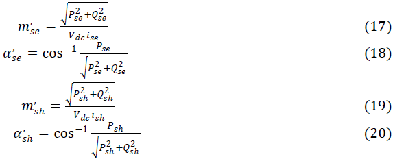
| The controller block for the series and shunt converters of UPFC are shown in Figs. 3(a) and (b). Pse0, Qse0, Psh0
and Qsh0 are the initial values of real and reactive power for series and shunt converters. The mse, αse, msh, and αsh are
provided to the PWM generator, which generates the gating signals for the power electronic switches in the series and
shunt converters. They obtained by m’se, α’se, m’sh, and α’sh by its 1st order lag process, respectively, which can be
expressed as |
 |
| and |
 |
 |
 |
 |
 |
THE PROPOSED NIDC FOR UPFC |
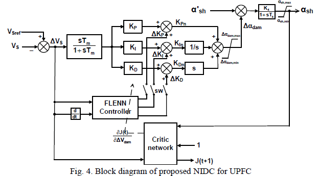
The proposed NIDC consists of three parts: the adaptive critic network, the FLENN and PID linear damping
controller, as shown in Fig. 4. The designed NIDC provides the training signal  to αsh of the UPFC shunt
converter to improve the OWF system stability. An FLNN is adopted to implement the function expansion for the FLbased
ENN to improve the accuracy of the function approximation. The adaptive critic network [16], [17] is applied in
order to provide suitable training signals for the FLENN controller. The FLENN produce the variation gains values
(ΔKP, ΔKI and ΔKD) of PID controller. The proposed NIDC is capable of providing near optimal results for complex
and uncertain nonlinear system in order to solve the Hamilton–Jacobi–Bellman equation of optimal control [16], [17]. to αsh of the UPFC shunt
converter to improve the OWF system stability. An FLNN is adopted to implement the function expansion for the FLbased
ENN to improve the accuracy of the function approximation. The adaptive critic network [16], [17] is applied in
order to provide suitable training signals for the FLENN controller. The FLENN produce the variation gains values
(ΔKP, ΔKI and ΔKD) of PID controller. The proposed NIDC is capable of providing near optimal results for complex
and uncertain nonlinear system in order to solve the Hamilton–Jacobi–Bellman equation of optimal control [16], [17]. |
 |
| A. PID linear damping controller |
| The PID damping controller is analysis of complex eigenvalues based on a theory of modal control. The matrix of
state space and the transfer function are follows as [18]. |
 |
 |
| The winds peed is set 14 m/s for designing PID damping controller the UPFC, the transfer function T(s) [18] is
represented as |
 |
| where Tm is the time constant of the washout filter. KP, KI and KD are the gains for PID controller. |
 |
 |
| B. FLENN |
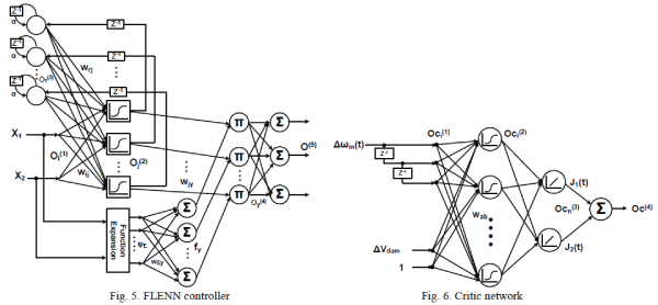
| Fig. 5 shows the design of the FLENN. It has an input layer, a hidden layer with a sigmoid function S(x)=1/(1 + e−x ),
a context layer, and an output layer that is connected with an FLNN. The context layer is fed back to itself with a time
delay z-1. The FLNN uses a feedforward neural network structure to generate a set of linearly independent functions,
and functionally expands the elements of the input variables. The trigonometric function is used in the FLNN, since it
can be computed more quickly than the Gaussian, sine and cosine functions. The input vector X=[X1, X2]T, which is a functional expansion that uses a trigonometric polynomial basis function, can be written in the enhanced space as
ψ=[ψ1, ψ2,…ψp]=[1, X1, sin(πX1), cos(πX1), x2, sin(πX2), cos(πX2), X1X2], where X1X2 is the outer product term.
Furthermore, the FLNN output is expressed by a linear sum of the yth node, as follows: |
 |
 |
The FLENN input  is used by the power system to directly transmit the numerical inputs to the next
layer in this study. The context neurons of FLENN serve as memory units, as they store the hidden layer output signal.
Therefore, the FLENN can employ the context neurons to increase dynamic characteristics of the network. The node
output of the each layer of the FLENN and the superscripts present the layer-number of the output O, while the
subscripts present the signal number of the related output, and these are given as follows. is used by the power system to directly transmit the numerical inputs to the next
layer in this study. The context neurons of FLENN serve as memory units, as they store the hidden layer output signal.
Therefore, the FLENN can employ the context neurons to increase dynamic characteristics of the network. The node
output of the each layer of the FLENN and the superscripts present the layer-number of the output O, while the
subscripts present the signal number of the related output, and these are given as follows. |
 |
| where the wij is the connecting weights of the input layer to the hidden layer, while wrj is the connecting weights of the
context layer to the hidden layer. α is the self-connecting feedback gain (0~1) of context neurons, and wjy is the
connecting weight between the hidden layer and multiplication layer. The link weight wo at output layer is unity. The
objective of the FLENN controller is to train the parameters wij, wrj, wjy and wEy to make the best match with regard to
the control signal O(5) to generate ΔKP, ΔKI and ΔKD. |
 |
| C. Critic network |
| A critic network can be continuously trained forward in order to learn the cost-to-go function associated with the
power system. This ability is of great importance for real time optimal control operations when there are changes in
configuration and operating conditions. The cost-to-go function J of Bellman’s equation of dynamic programming
estimated by the critic network is as follows [14]. |
 |
| where the utility function U(t) is an important effect to form the optimal cost-to-go function. γrepresents the
discount factor (0~1). The utility function of the critic network is U(t), as follows. |
 |
| The node output of the each layer of the critic network and the superscripts represent the layer-number of the output
Oc, while the subscripts present the signal number of the related output, and these are given as follows. |
 |
| where wab is the connecting weights of the input layer to hidden layer. |
| Using Eq. (34), the UPFC should improve the performance of bus voltage deviation ΔVS. The critic network in Fig. 6
has a four-layer feed-forward network structure. The training process ensures that the critic network provides optimal
control to minimize the J(t), which enables the FLENN controller to provide the optimal parameters of PID controller
to the UPFC in this paper. |
| D. The training process of FLENN and critic network |
| The gradient of the error function is the direction to which the function increases. Therefore, searching the opposite
side of the gradient can force the cost-to-go function to be minimized. The gradient descent algorithm with the mean
squared error function as the error function E can be defined by [16] |
 |
| where the J*(t) is the reference value of the cost-to-go function, which in the case of dealing with deviation signals is
zero. |
| The changes in direct proportion to the amount that weights wab are modified, and can be used to produce the
instantaneous estimates of the negative gradient. In order to use an on-line algorithm for the critic network and
proposed FLENN, the gradient based on the chain rule can be represented as (40) and (41). The formulae for adjusting
the wab of the critic network and weights WFLENN of FLENN are shown in by (42) and (43). |
 |
 |
CASE STUDIES AND SIMULATIONS |
| The proposed NIDC were simulated in this section. The damping controllers of SMIB plus the OWF system
are compared with and without UPFC, with UPFC plus PID controllers while SW off, and with UPFC joined
with the proposed NIDC while SW on in Fig. 4. The power system in Fig. 1 is simulated using PSCAD
software, while the FLENN and critic network with GACO are achieved in a MATLAB 7.0 program. Three cases are
described here to illustrate the proposed method. |
| Case A: The stability of changes in wind speed |
| The wind speed is assumed to change from 14 m/s to 11 m/sat the 10th second, from 10 m/s to 19 m/s
at the 15th second and from 19 m/s to 14 m/s at the 17th second in Fig. 7(a). Figs. 7(b) and (c) show
the responses of the real and reactive powers of Line 2, respectively. It is found that the real
and reactive powers of the OWF change with the variations of wind speed. When the UPFC is in
service, the amplitudes of the real and reactive power changes can be reduced, and thus better
control is achieved. The smallest amplitude changes on the real and reactive powers of Line 2 can
be obtained when the proposed NIDC is installed with the UPFC. Similar amplitude results can be
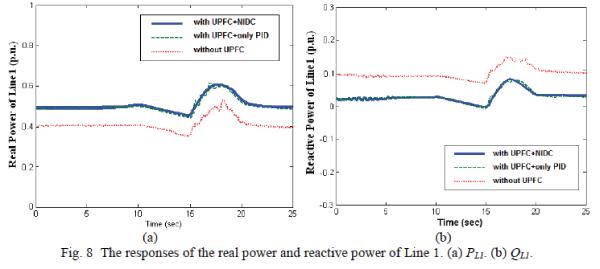
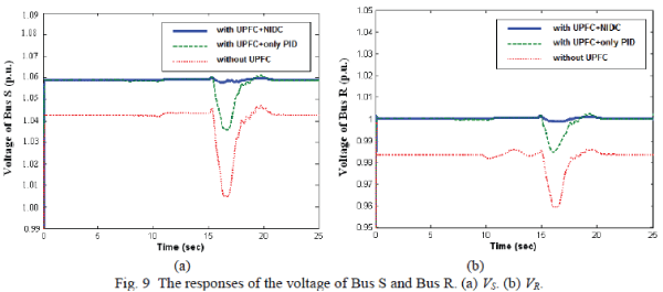
found from the real and reactive powers of Line 1 shown in Figs. 8(a) and (b). Figs. 9(a) and (b)
show the responses of the voltage magnitudes of Bus S and Bus R, respectively. When the wind speed changes, the voltage magnitudes of Bus S and Bus R can also be found at the desired level. The
voltage magnitudes of the two buses have the smallest variations when the proposed NIDC is
joined with the UPFC. |
| Case B: Transient stability of the three phase fault |
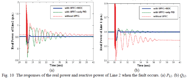
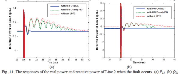
| A three-phase short circuit with a duration of 0.1secondis simulated at the 30th second. The fault is
used to compare the damping characteristics of the proposed scheme. When a fault occurs, Figs.
10(a) and (b) show that the UPFC with a PID controller (green line) can have better damping
performance with regard to the real and reactive power on Line2 than the system without UPFC
(red line). It can be also seen that the proposed NIDC for UPFC (blue line) has the best
damping effect on the transient stability for both real and reactive powers. Similar stability
improvements can be also found from the transient stability of the real and reactive powers of Line 1
shown in Figs. 11(a) and (b). Figs. 12(a) and (b) also show that the UPFC with the NIDC can
effectively improve the voltage transient stability of Bus S and Bus R. Fig. 12 (c) shows that the
rotor speed of the wind PMSG (ωr) can quickly recover to the corresponding steady state when the
system has the UPFC installed with NIDC, with better results than are seen with the systems
that have UPFC plus only PID controller and without UPFC. |
 |
 |
 |
 |
 |
 |
CONCLUSION |
| The results reported in this paper demonstrate the effectiveness of the proposed designed PID controller and NIDC
for a UPFC with regard to improving the power control and stability of a grid containing a large-scale OWF and SG.
The transient responses of the studied system subject to a three-phase short circuit fault show the effectiveness of the
proposed method. Moreover, the online learning algorithms of the connective weights deviations of proposed FLENN
and critic network were derived in this work. The control performance of the proposed NIDC shows that the method
presented in this work can effectively stabilize the network under unstable conditions. |
APPENDIX |
 |
References |
- Shariatpanah H., Fadaeinedjad R., and Rashidinejad,M. âÃâ¬ÃÅA New Model for PMSG-Based Wind Turbine With Yaw ControlâÃâ¬ÃÂ, IEEE EnergyConvers., vol. 28, no. 4, pp 929-937, 2013
- Senjyu T., Sakamoto R., Urasaki N., Funabashi T., and Sekine H., âÃâ¬ÃÅOutput power leveling of wind farm using pitch angle control with fuzzyneural networkâÃâ¬ÃÂ', in Proc. Power Eng. Soc. Gen. Meeting., Jun. 2006.
- Sakamoto R., Senjyu T., Kaneko T., Urasaki N., Takagi T., Sugimoto S., and Sekine H., âÃâ¬ÃÅOutput power leveling of wind turbine generator bypitch angle control using H8 controlâÃâ¬ÃÂ, IEEE Trans. Power Syst., pp 2044-2049, 2006.
- Lin W. M., Hong C. M., Ou T. C., and Chiu T. M., âÃâ¬ÃÅHybrid intelligent control of PMSG wind generation system using pitch angle control withRBFNâÃâ¬ÃÂ, Energy Convers. and Mana., vol. 52, no.2, pp 1244-1251, 2011
- Hingorani N. G. and Gyugyi L., âÃâ¬ÃÅUnderstanding FACTS, Concepts and Technology of Flexiable AC Transmission SystemsâÃâ¬ÃÂ. IEEE PowerEngineering Society and CIGRE, "FACTS overview" IEEE publication No. 95 TP 108, 1995.
- Farrag M. E. A., and Putrus G. A., âÃâ¬ÃÅDesign of an Adaptive Neurofuzzy Inference Control System for the Unified Power-Flow ControllerâÃâ¬ÃÂ,IEEE Trans. Power Del., vol.27, no.1, pp 53-61, 2012.
- Ajami A., M.Shotorbani A., and M Aagababa. P., âÃâ¬ÃÅApplication of the direct Lyapunov method for robust finite-time power flow control with aunified power flow controllerâÃâ¬ÃÂ, IET Gener. Transm. Distrib., vol.6, no.9, pp 822-830, 2012.
- Malhotra U., and Gokaraju R., âÃâ¬ÃÅAn Add-On Self-Tuning Control System for a UPFC ApplicationâÃâ¬ÃÂ, IEEE Trans. Industrial Electronics, vol.61,no.5, pp 2378-2388, 2014
- Mehraeen S., Jagannathan S., and row C M. L., âÃâ¬ÃÅNovel Dynamic Representation and Control of Power Systems With FACTS DevicesâÃâ¬ÃÂ, IEEETrans. Power Syst., vol.25, no.32, pp 1542-1554, 2010
- Shayeghi H., Shayanfar H., Jalilzadeh S., and Safari A., âÃâ¬ÃÅDesign of output feedback UPFC controller for damping of electromechanicaloscillations using PSOâÃâ¬ÃÂ, Energy Convers., vol. 50, no. 10, pp 2554-2561, 2009
- Seethalekshmi K., Singh S. N., and Srivastava S. C., âÃâ¬ÃÅSynchrophasor Assisted Adaptive Reach Setting of Distance Relays in Presence ofUPFCâÃâ¬ÃÂ, IEEE Systems Journal, vol.5, no.3, pp 396-405, 2011
- Lin W. M., Hong C. M., Huang C. H., and Ou T. C., âÃâ¬ÃÅHybrid Control of a Wind Induction Generator Based on GreyâÃâ¬ÃâElman Neural NetworkâÃâ¬ÃÂ,IEEE Trans. Control Systems Tech., vol. 21, no. 6, pp 2367âÃâ¬Ãâ2373, 2013
- Toh K. A. and Yau W. Y., âÃâ¬ÃÅFingerprint and speaker verification decisions fusion using a functional link network,âÃâ¬Ã IEEE Trans. Syst., Man,Cybern. C, Appl. Rev., vol. 35, no. 3, pp. 357âÃâ¬Ãâ370, Aug. 2005.
- Chaturvedi K. T., and Pandit M., and Srivastava L., âÃâ¬ÃÅSelf-Organizing Hierarchical Particle Swarm Optimization for Nonconvex EconomicDispatchâÃâ¬ÃÂ, IEEE Trans. Power Syst., vol. 23, no. 3, pp 1079-1087, 2008
- Trilla, L., Bianchi, F. D., Gomis-Bellmunt, O.; 'Linear parameter varying control of permanent magnet synchronous generators for wind powersystems', IET Power Electr., 2014, 7, (3), pp 692-704
- Swaksharand R., and Ganesh K. V., âÃâ¬ÃÅWide-Area Signal-Based Optimal Neurocontroller for a UPFCâÃâ¬ÃÂ, IEEE Trans. Power Del., vol. 2, no. 3,pp 1597-1605, 2008
- Xu X., Hou Z., Lian C., and He H., âÃâ¬ÃÅOnline Learning Control Using Adaptive Critic Designs With Sparse Kernel MachinesâÃâ¬ÃÂ, IEEE Trans. Neu. Net. and Lear. Syst., vol. 24, no. 5, pp. 762-775, 2013
- Fan L. and Miao Z., âÃâ¬ÃÅMitigating SSR Using DFIG-Based Wind GenerationâÃâ¬ÃÂ, IEEE Trans. Sust. Ener., vol. 3, no.3, pp. 2297-2302, 2012
|