International Journal of Innovative Research in Science, Engineering and Technology
ISSN ONLINE(2319-8753)PRINT(2347-6710)
ISSN ONLINE(2319-8753)PRINT(2347-6710)
Md Shahid Imam1, Dr.M.Shameer Basha2, Dr.Md.Azizuddin3, Dr. K.Vijaya Kumar Reddy4
|
| Related article at Pubmed, Scholar Google |
Visit for more related articles at International Journal of Innovative Research in Science, Engineering and Technology
Transportation is one the need of human being, which is existing since the evolution of mankind. Today, the field of air conditioning design is more technologically challenging than ever before. In the present the design of air conditioning is done for a Volvo bus, a fully equipped automotive air-conditioning system consists of five main components: a compressor, a condenser, an orifice tube, an evaporator and an accumulator. R-134a is used as refrigerant by considering the various parameters.
Keywords |
| Automotive; Air conditioning; R-134a; |
INTRODUCTION |
| Compared with other air conditioning (A/C) systems, automotive A/C systems have some significant characteristics. Automotive A/C systems present challenges not normally encountered in stationary A/C systems, such as those used in building A/C systems. In general air conditioning is defined as the simultaneous control of temperature, humidity, cleanliness and air motion. Depending upon the requirement, air conditioning is divided into the summer air conditioning and the winter air conditioning. The former uses a refrigeration system and a dehumidifier against a heat pump In addition, air conditioning is also sub divided into the comfort and industrial air conditioning. The former deals with the human comfort which as well, requires noise control while the latter is meant for the production of an environment suitable for commercial products or commodities, production shop laboratories, manufacture of materials and precision devices, printing works, photographic products, cold storages, computers, etc |
II.DESCRIPTION OF EXPERIMENTAL SETUP |
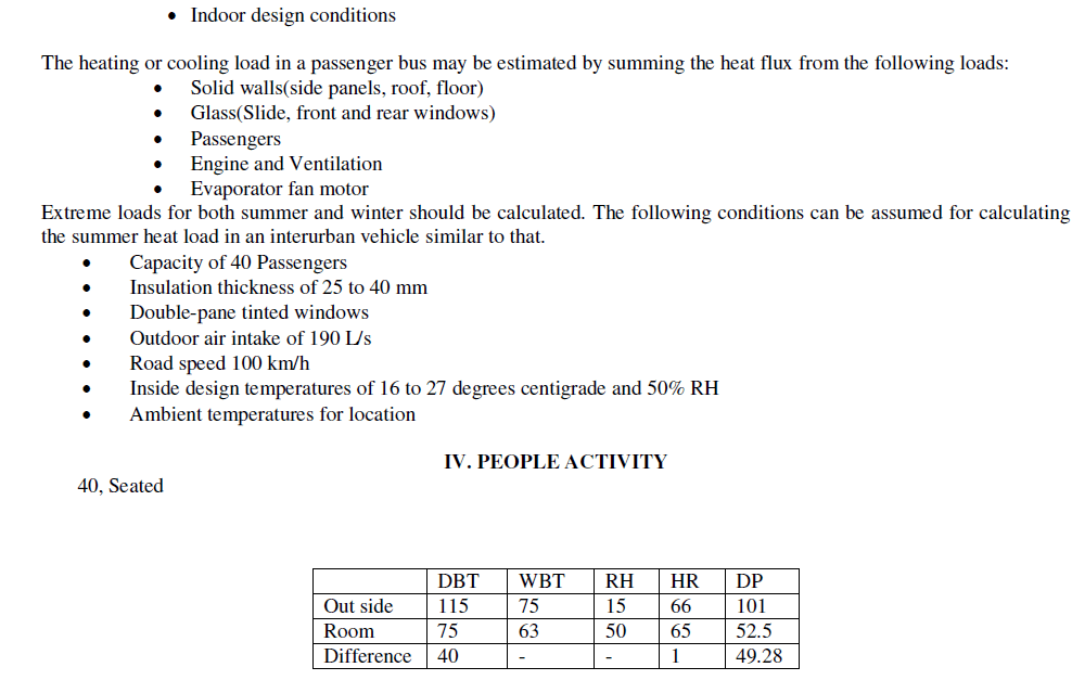
| There are two main types of automotive air-conditioners: one is a Thermal Expansion Valve (TXV) system which regulates rate of refrigerant flow into evaporator as governed by evaporator outlet pipe temperatures sensed by the sensing bulb, and the other is Clutch Cycling Orifice Tube (CCOT) system which controls evaporator temperature by turning the compressor on and off with a clutch cycling switch. A CCOT automotive A/C system includes a compressor, a condenser, an expansion device, an evaporator and an accumulator as shown in Figure1. The schematic diagram of the experimental setup used in this experimental investigation is shown in Figure 2 |
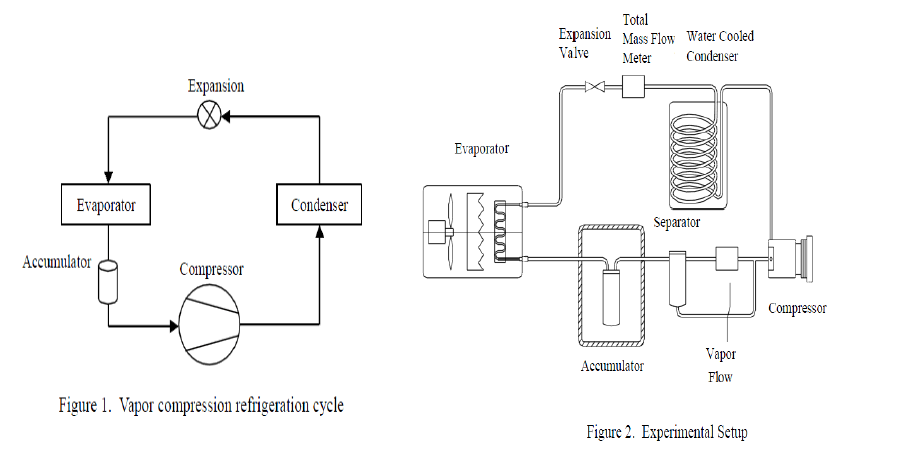 |
| It is a closed refrigeration loop charged with R-134a (1,1,1,2-Tetrafluoethane) as working fluid and built to operate as a CCOT system. The main components are a compressor stand, a water-cooled condenser stand, an evaporator stand, two mass flow meters, an accumulator stand, a separator, and various process instruments. The compressor stand consists of a typical automotive swashplate type compressor driven by a 10 HP variable-speed electric motor. A one-to-one pulley ratio was used to connect the electric motor to the compressor. The water-cooled condenser stand consists of a helical coil of half-inch diameter aluminum pipe as condenser, a water bath, a water pump, a valve, and temperature controller. A mass flow meter was installed at the condenser outlet to measure the total mass flow rate of the refrigerant–lubricant oil flow. The compressor is lubricated using Polyakylene-glycol (PAG). A sight glass tube is placed at the outlet of the flow meter to ensure that the flow meter chamber was filled with sub-cooled liquid refrigerant–PAG oil single phase. An orifice tube is used as expansion device to change the higher pressure sub-cooled liquid refrigerant into lower pressure and temperature vapor-liquid mixture. The evaporator stand consists of an automotive evaporator, an electric heater, an air-blower to circulate the air inside the duct to simulate environmental conditions, and a temperature controller to keep the air at a certain temperature. The evaporator stand was well insulated so that the power input from heater is considered as the same as cooling capacity. The accumulator stand consists of an accumulator, an electric heater to simulate environment temperature, a temperature controller to keep the air at a certain temperature, and an insulated box to contain these components. A sight glass tube is placed at the outlet of the accumulator for observing the refrigerant−PAG oil flow (twophase). An aluminum pipe, 1.2 m long and 52 mm in diameter, is placed following the sight glass tube, which allows the annular flow to slow down and become separated. The flow separates completely in the liquid/vapor separator. The refrigerant vapor flows through the mass flow meter so that the vapor flow rate was measured. A sight glass tube at the outlet of mass flow meter ensures that the flow meter chamber was filled with vapor refrigerant only. Then, the vapor refrigerant and liquid refrigerant−PAG oil are mixed again at the inlet of compressor. To conduct data acquisition processing and control the operation of A/C system, a control and measurement system was set up, which includes thermocouples, sensors, transducers, data acquisition devices, signal conditioning extensions for instrumentation devices. By this system, the temperature and pressure at each component, mass flow rate, power, and compressor speed are measured as analog signals, and then the analog signals are converted to digital signals and sent to the computer to display windows directly or be processed to calculate other parameters. Second. This system also can control the operation of the air conditioning system, such as turning the power on or off, setting the temperature of evaporator and condenser, adjusting the compressor speed. Meters are placed at the inlet and outlet of the compressor to show the gauge pressure at these two locations. |
III. CALCULATION FOR TONNE OF COOLING REQUIRED FOR A VOLVO BUS DESIGN DATA: |
 |
 |
| This cooling load is calculated from three difference heat sources: |
| 1. Transmission of heat through the BUS body structure QT = 0.19 kW |
| 2. Solar heat gain through the wind-screen and side windows QR = 0.44 kW |
| 3. Internal heat gains QI = 0.50 kW Total QTOT = 1.13 kW |
V. CONCLUSIONS |
| With the experimental set-up, some results have been obtained which revealed some unknown aspects of the automotive air conditioning systems. The following remarks summarize some key performance characteristics of an automotive airconditioning system with an accumulator. 1. Design of Air conditioning system in auto mobiles is done successfully for VOLVO bus. The parameters of the bus are 3200 cu.ft . Finally the output obtained is 8.25 TR. The VOLVO bus considered is having Comfortable application. The aim of the Project is achieved by the designing. |
| 2. The total mass flow rate of circulation in an automotive air conditioning system increases with the increase of refrigerant charge, evaporator air-side temperature and condenser water temperature. The total quality at the accumulator outlet increases with the increase of evaporator air-side temperature, and decreases with the increase of refrigerant charge and condenser water temperature. |
| 3. The cooling capacity does not change with the variation of refrigerant charge, but increases with the increase of evaporator air-side temperature, and decreases with the increase of condenser water temperature. Coefficient of performance of the system decreases with the increase of refrigerant charge and Condenser water temperature, increases with the increase of evaporator air-side temperature. |
| 4. The compression ratio decreases with the increase of refrigerant charge and evaporator air-side temperature, increases with the increase of condenser water temperature. The change of compressor Volumetric efficient is opposite to that of compression ratio. |
References |
|