ISSN ONLINE(2319-8753)PRINT(2347-6710)
ISSN ONLINE(2319-8753)PRINT(2347-6710)
Dhiren Ramanbhai Patel1, Vivek Parekh2, Vaibhav Panchal2, Sanjay Pipaliya2
|
| Related article at Pubmed, Scholar Google |
Visit for more related articles at International Journal of Innovative Research in Science, Engineering and Technology
Generally, manufacturers perform quenching of copper & its alloys pipes right after their extrusion from press. For better grains structure & efficient cooling of pipes, hot pipes are kept into water for a while. Cooling occurs due to heat exchange between quenching fluid & hot pipe by conduction and between hot water & surroundings by natural convection. Since the process of extrusion is continues, quenching of pipes must also be continues .However, conduction leads to rise in temperature of quenching fluid ,which in turn, adversely affects the continuity of the process. Also, rise in surrounding temperature affects worker's ability. To prevent these negative effects, we have to stop all processes until the temperature of hot water does not come into equilibrium to atmospheric temperature. Thus, low heat loss rate of quenching fluid poses problems during continues process. Therefore, Heat loss rate should be rapid & continues. To achieve this purpose, our objective is to design a cooling tower as per requirements, and measure its performance during process of heat exchange & quenching of pipes
Keywords |
| Heat exchanger, Quenching, Kern Method, Hardening. |
INTRODUCTION |
| Extrusion Process begins by heating the stock material. The material is then loaded into the container in the press. A dummy block is placed behind it where the ram then presses on the material to push it out of the die. If better properties are required then it may be heat treated or cold worked. The extrusion ratio is defined as the starting cross-sectional area divided by the cross-sectional area of the final extrusion. One of the main advantages of the extrusion process is that this ratio can be very large while still producing quality parts. In industry, molten metal is cooled to form the solid. The solid metal is then mechanically shaped to form a particular product. How these steps are carried out is very important because heat and plastic deformation can strongly affect the mechanical properties of a metal. It has long been known that the properties of some metals could be changed by heat treating. Grains in metals tend to grow larger as the metal is heated. There are many ways in which metals can be heat treated. Quenching results in a metal that is very hard but also brittle. Gently heating a hardened metal and allowing it to cool slowly will produce a metal that is still hard but also less brittle. This process is known as tempering. Quenching is an accelerated method of bringing a metal back to room temperature, preventing the lower temperatures through which the material is cooled from having a chance to cause significant alterations in the microstructure through diffusion. Quenching can be performed with forced air convection, oil, fresh water, salt water and special purpose polymers. |
II. QUENCHING PROCESS |
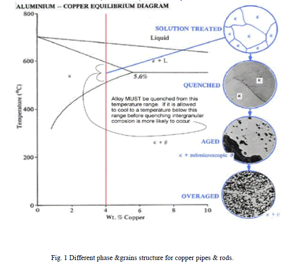
| A. Quench Hardening Quench hardening is a mechanical process in which copper and its alloys are strengthened and hardened by either surface hardening or through-hardening varying on the rate at which the material is cooled. This is done by heating the material to a certain temperature, depending on the material. The material is then often tempered to reduce the brittleness that may increase from the quench hardening process. Items that may be quenched include gears, shafts, and wear blocks. B. Process The first step in Quenching is heating to the required temperature. Next step is soaking. Soaking can be done by air (air furnace), or a bath or in a vacuum. The soaking time in air furnaces should be 1 to 2 minutes for each millimeter of cross-section. For a bath the time can range a little higher within a vacuum, soak is generally similar to in air. Uneven heating or overheating should be avoided at all cost. Most materials are heated from anywhere to 815 to 900 °C (1,500 to 1,650 °F).The next item on the progression list is the cooling of the part. To minimize distortion, long cylindrical work pieces are quenched vertically; flat work pieces are quenched on edge; and thick sections should enter the bath first. To prevent steam bubbles the bath is agitated. High Pressure Gas Quenching (HPGQ) offers far better possibilities of work piece distortion control by controlling the pressure, wind speed, wind direction as well as the actual gas used. C. Effect Before the material is hardened, the microstructure of the material is a pearlite grain structure that is uniform and lamellar. Pearlite is a mixture of ferrite and cementite formed when steel or cast iron are manufactured and cooled at a slow rate. After quench hardening, the microstructure of the material form into martensite as a fine, needle -like grain structure. Before using this technique it is essential to look up the rate constants for the quenching of the excited states of metal ions. Sometimes an image may contain text embedded on to it. Detecting and recognizing these characters can be very important, and removing these is important in the context of removing indirect advertisements, and for aesthetic reasons. D. Equipment There are four types of furnaces that are commonly used in quench hardening: salt bath furnace, continuous furnace, box furnace and vacuum furnace. Each is used depending on what other processes or types of quench hardening are being done on the different materials. E. Quenching media Water is one of the most efficient quenching media where maximum hardness is acquired, but there is a small chance that it may cause distortion and tiny cracking. The water should have no impurities such as oil, grease or acids as they could result in uneven hardening. Apart from water, other quenchants are whale oil, cottonseed oil and mineral oils. Oil bath quenching is used where extreme hardness is not required and where freedom from quenching shock is needed. Oil cooling systems are required when significant quenching capacity is required to prevent the oil from breaking down and to maintain the quenching conditions. However, oils often oxidize and form a sludge, which consequently lowers the efficiency. Another disadvantage of oils is that the quenching velocity (cooling rate) of oil is much less than water. Air cooling is used for mild hardening process when a tough hard pearlitic structure is required. Quenching can also be accomplished using inert gases. Most commonly, nitrogen is used at pressures greater than atmospheric pressure ranging up to 20 bars absolute. Helium is also used because of its greater thermal capacity than nitrogen. Alternatively argon can be used however its density requires significantly more horsepower to move it and its thermal capacity is less. F. Quenching distance It is defined as the smallest hole a flame can travel through. For example hydrogen has a quenching distance of 0.64 mm. G. Problems during the quenching process We are using quenching fluid which have boiling point of 45000C to 50000C.The extruded hot copper pipe having temperature of 60000C to 70000C which is recrystallization temperature of copper substance. When hot pipe come directly into contact with fluid due to temperature difference heat transfer will takes place & it will establish quenching heat treatment. This offers appropriate grains structure, efficient hardening & other crucial properties. (1) As soon as long continuous process takes place the temperature of fluid increases & provide inefficient quenching to succeeding pipe. (2)Higher temperature fluid exchanging heat with surrounding too, which results in surrounding temperature raise. Due to first problem Quality of pipes & Rods structure do not maintain at required level. In second surrounding temperature increment causes reduction in workers ability, increment in room temperature. |
 |
III. HEAT EXCHANGER |
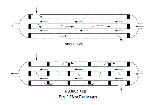
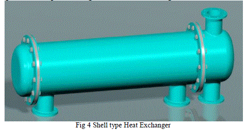
| Heat exchangers are used for the purpose of transmitting heat from a hot fluid to a colder fluid under all conditions of temperature and pressure. In the equipment, the hot and cold media are separated by a solid boundary wall keeps the two fluids apart and permits heat to flow from the hot to the colder fluid. Mostly, this boundary is a metal tube or pipe wall. The most common mechanism by which heat is transferred is forced convection, since both fluids are usually under forced flow. The type that is discussed in this paper is shell and tube exchangers. They are designed as per “Tubular exchangers manufacturers association" (TEMA). In TEMA, the exchangers are classified as class R, class C, or class B depending upon type of service. |
 |
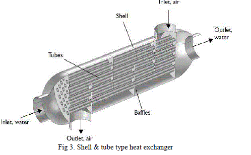 |
| A. Mechanical Process 1. Selection of heat exchanger TEMA layout and number of passes. 2. Specification of tube parameters - size, layout, pitch and material. 3. Setting upper and lower design limits on tube length. 4. Specification of shell side parameters – materials, baffles cut, baffle spacing and clearances. 5. Setting upper and lower design limits on shell diameter, baffle cut and baffle spacing. B. Basic theory |
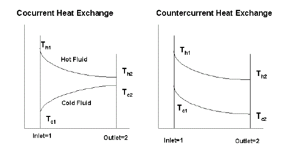 |
| Where, Q = heat transferred per unit time (kJ/h, Btu/h), U = the overall heat transfer coefficient (kJ/h-m2âÃâÃÆ, Btu/h-ft2- ºF), A = heat-transfer area (m2, ft2), Δtlm = log mean temperature difference (âÃâÃÆ, ºF), Cp (t) = liquid specific heat tube side, Cp(s) = liquid specific heat shell side, W = tube side flow W shell side flow (kg/h, lb/h), the log mean temperature difference ΔTlm (LMTD) for counter current flow is given by Where T1= inlet shell side fluid temperature, T2 = outlet shell side fluid temperature, t1 = inlet tube side temperature, t2 = outlet tube-side temperature. The log mean temperature difference ΔTlm (LMTD) for counter current flow is given by: |
 |
 |
IV. DESIGN OF HEAT EXCHANGER USING THE KERN METHOD |
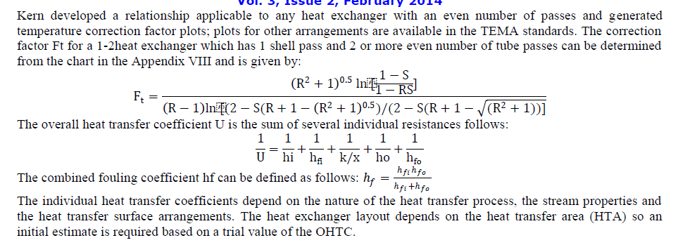
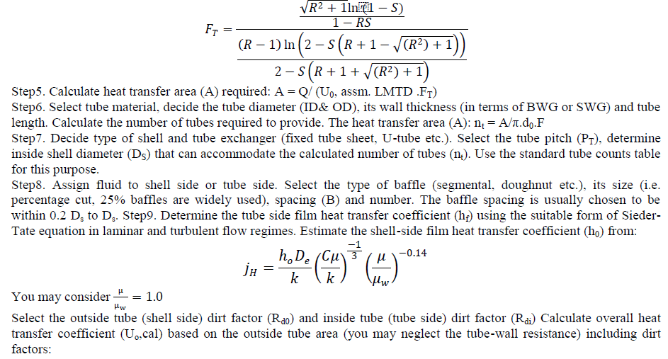
| In our case, the heat exchanger will be made with using The Kern Method. Kern adapted the Nusselt equation to allow evaluation of fluid conditions at the film temperature. This method requires the film to be in streamline flow with a Reynolds Numbers range 1800 to 2100. Step1. Obtain the required thermo physical properties of hot and cold fluids at the caloric temperature or arithmetic mean temperature. Calculate these properties at the caloric temperature if the variation of viscosity with temperature is large. The detailed calculation procedure of caloric temperature available is in reference. Step2. Perform energy balance and find out the heat duty of the exchanger. Step3. Assume a reasonable value of overall heat transfer coefficient (Uo, assm). The value of Uo, assm with respect to the process hot and cold fluids can be taken from the study materials. Step4. Decide tentative number of shell and tube passes. Determine the LMTD and the correction factor FT. FT normally should be greater than 0.75 for the steady operation of the exchangers. Otherwise it is required to increase the number of passes to obtain higher FT values. |
 |
 |
| A= design area of heat transfer in the exchanger; Areq = required heat transfer area. Step12. Calculate the tube-side pressure drop (ΔPT): (i) pressure drop in the straight section of the tube (frictional loss) (ΔPt) and (ii) return loss (ΔPrt) due to change of direction of fluid in a multi-pass exchanger. Total tube side pressure drop: ΔPT = ΔPt + ΔPrt Step13. Calculate shell side pressure drop (ΔPs): (i) pressure drop for flow across the tube bundle (frictional loss) (ΔPs) and (ii) return loss (ΔPrs) due to change of direction of fluid. Total shell side pressure drop: ΔPs = ΔPs+ ΔPrs If the tubeside pressure drop exceeds the allowable pressure drop for the process system, As Step 6 and repeat the calculations steps. If the shell-side pressure drop exceeds the allowable pressure drop, go back to step 7 and repeat the calculations steps. step14. Upon fulfillment of pressure drop criteria, go to mechanical design. |
 |
V. CONCLUSION |
| In this paper, experimental study of shell-and-tube heat exchanger is conducted to calculate the heat transfer coefficient, LMTD, Nusselt number, and pressure drop at different Reynolds numbers. The Kern Method of designing heat exchanger. It is concluded that the hot quenching fluid & cooling fluid have a significant impact on different parameters of shell-and-tube type heat exchanger. The major findings are summarized as follows. |
| 1. The design variables which are used for the shell and tube heat exchanger are tube inside diameter, tube outside diameter, number of tubes, baffle spacing and tube pitch etc. The analysis of these design parameters is very important for the better performance of shell and tube heat exchanger. |
| 2. The heat transfer coefficient increases with increase in Reynolds number in shell-and-tube heat exchanger for both hot fluid inlet and cold fluid inlet. |
| 3. It was found that cold fluid outlet temperature decreases and the Overall heat transfer coefficient increases with increase in flow rate of cold fluid. |
| 4. The outlet temperature of cold fluid decreases and overall heat transfer coefficient increases with increase in composition of water. The overall effectiveness of heat exchanger was found to increase with decrease in composition of water. |
References |
|