ISSN ONLINE(2319-8753)PRINT(2347-6710)
ISSN ONLINE(2319-8753)PRINT(2347-6710)
Prem Kumar Chaurasiya 1, Jaydeep Lakwal 2, Manish Singh Bharti 3
|
| Related article at Pubmed, Scholar Google |
Visit for more related articles at International Journal of Innovative Research in Science, Engineering and Technology
Hydrogenation is one of the oldest technologies for harnessing electricity from water. In order to control the power harvested from water, conventionally small scale hydro-power station uses a fixed speed drive with mechanical regulation. This conventional arrangement is expensive and is not affordable for small scale hydro-power plant. In this paper, an advanced configuration of a micro-hydro power plant (MHPP) is proposed, which is more efficient, lighter and smaller. The proposed design is quite simple and it eliminates the mechanical adjustment with the help of an efficient Power electronic System (PES). The designed topology consists of a five-level Transistor Clamped Multilevel Inverter (TCMLI) that allows the efficient and reliable generation of high quality electric power from the MHPP at lower costs. A detailed model of the MHPP is derived and five-level control scheme is designed. Results are verified by computer simulation.
Keywords |
| Micro-hydro power plant (MHPP), Power Electronic System (PES), Transistor clamped multilevel inverter (TCMLI), Pulse-width modulation (PWM), Total Harmonic Distortion (THD). |
INTRODUCTION |
| The ever increasing world energy demand cannot be fulfilled much longer with fossil fuels hence the leading countries have strongly focused on the enhancement of renewable energy sources [1]. The advantage of using modern technology finds the solutions for ecological reason, energy parameters and economical factors. The idea of using clean technologies of generation that uses renewable energy sources restrict the environmental pollution, such as wind, photovoltaic, hydraulic and among others[2]. In this computational era, multilevel inverter is implemented in various applications, such as motor drives, power electronic systems and conventional or renewable energy generation as well as distribution systems. Multilevel inverter (MLI) attracted the attention of academic and industries [3-4]. Because the demand for medium voltage, high power inverters are capable of generating quality waveforms while using low voltage devices and reduced switching frequencies led to the development of multilevel inverter. MLI decreases harmonic contents in output waveforms without decrease in output power. Research in the field of multilevel inverter is going to further improvement in its capability, to optimize control techniques, and to minimize both number of component and manufacturing cost [5]. To enable high-power conversion, power cells are typically cascaded in series and configured in multilevel structures. The synthesized multilevel outputs are superior in quality which led to the reduction of filter requirement and size of the system. Recently transistor clamped inverter topology is get attention by researchers as it generates higher number of levels as compare with conventional H-bridge. In this paper, an advanced configuration of a micro-hydro power plant (MHPP) is proposed, which is more efficient, lighter and smaller. The proposed design is quite simple and it eliminates the mechanical adjustment with the help of an efficient Power electronic System (PES). The designed topology consists of a five-level Transistor Clamped Multilevel Inverter (TCMLI) that allows the efficient and reliable generation of high quality electric power from the MHPP at lower costs [6]. A detailed model of the MHPP is derived and five-level control scheme is designed. The model includes hydraulic turbine directly coupled to a synchronous generator and the PES is made up of an AC/DC/AC converter configuration. The configuration of transistor clamped multilevel inverter (TCHMLI) is discussed using MATLAB based simulation. Multicarrier phase disposition pulse width modulation (PDPWM) technique and Harmonic analysis (THD) is presented. |
| This paper is organized as follows: Section II presents the dynamic model of the proposed micro-hydro power plant, and Section III demonstrates the transistor clamped multilevel inverter. Section IV discusses control technique of MHPP. Section V shows simulation results followed by conclusion in the Section VI. |
MODEL OF THE PROPOSED MICRO-HYDRO POWER PLANT |
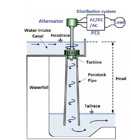
| The proposed hydropower station does not require water reservoir such as large dams. As a result, this leads to a good environmental surrounding and also permits the utilization of water sources from low head. In order to provide flexibility to adapt to the specific condition of river with low discharge, variable speed turbines seems to be the best alternative. The hydropower station is integrated into the electric power grid to extend the control features and quality of output by reducing certain harmonics. Higher reliability stations with better efficiencies can be attained by replacing mechanical control with power electronics technologies [7]. The detailed modelling of micro-hydro power plant [8] is illustrated in Fig.2. Permanent magnet synchronous generator (PMSG) is directly coupled to micro hydro turbine of a variable speed and a novel power electronic system (PES) is connected to a load. The proposed PES is composed of a 3-phase rectifier bridge and a 5-level Transistor Clamped Z-Source Multilevel Inverter. |
| 1. Hydraulic Turbine Characteristic: |
| This hydraulic turbine is a modified Kaplan turbine of propeller type, which is based suited for low water head and low discharging. The design is robust and simple in the absence of gear box for coupling to the generator. In order to obtained the based efficiency the design is made with an optimum swirl before the entrance of the turbine runner through appropriate setting of guide-vanes. Hydraulic power of output is given as |
 |
| The proposed hydraulic turbine can operate at low head, low discharge and over all range of rotor speeds. The turbine efficiency mainly depends upon the operating conditions (Q, H, ρ) and turbine design, and thus is very complex to determine analytically. |
| 2. Power Electronic System : |
| The proposed PES is made up a of back-to-back AC/DC/AC power converter. As shown in the layout that synchronous generator is directly coupled to the variable speed hydro turbine, this machine provides output voltage of variable amplitude and frequency. This condition demands the use of an extra system to meet the variable output requirements. A 3-phase uncontrolled full wave rectifier bridge is proposed here for AC-DC conversion. This device has the benefit of being cheap, robust, and simple and no need of control system. On the other hand, a 1-phase DC-AC transistor clamped multilevel inverter used here for AC output requirements. The output voltage is controlled through pulse width modulation (PWM) scheme. |
| As the MLI needs a fixed DC supply in order to a decoupled control of both active and reactive power exchange with load, an interface in the DC side of the MLI is required. For this purpose a DC-DC converter in a boost topology is employed. This arrangement replacing the conventional machine-side MLI by a simpler and lower cost interface. However, two-stage arrangement retains some drawback when compared to single-stage topologies, such as: |
| Lower efficiency of power conversion, because of two-stage configuration. |
| Higher weight and volume, since the boost stage increases system weight and size. |
| Reliability is lower because of controlled switches are used with the addition of the chopper. |
| On the other hand, due to the potential existence of shoot-through states arising from gate-drives failures, the reliability of one-stage and two-stage, both is reduced. Hence there is a new motivation to overcome these limitations. In order to overcome these drawbacks, this paper proposed a new topology capable of maintaining the output voltage with variation of the primary energy source and preserves a higher DC voltage of fixed magnitude, all in one stage, and at the same time taking benefit of the shoot-through states. This structure realizes both inversion and boost function in a single stage, is an impedance-fed power inverter. A unique impedance source consisting of a two port network with a couple of capacitors and inductors connected in X-shape is used with the proper design of the PWM scheme to the inverter for achieving the voltage boosting function independently and simultaneously of the inverter operation [9]. Multilevel inverters attract the attention of academic as well as industries. MLI are chosen for voltage of medium level and high power applications because of their advantages, like ability to meet the escalating demand of power rating and quality of power associated with reduced harmonic distortion, minor electromagnetic interference, and higher efficiency as compared to conventional 2-level inverters [10-11]. In this way, in order to provide an effective multilevel topological alternative for present inverter application, it is used a modified 5-level transistor clamped Z-source inverter supplied by one uniquely design Z-source impedance network as depicted in Fig.2. |
 |
TRANSISTOR CLAMPED MULTILEVEL INVERTER |
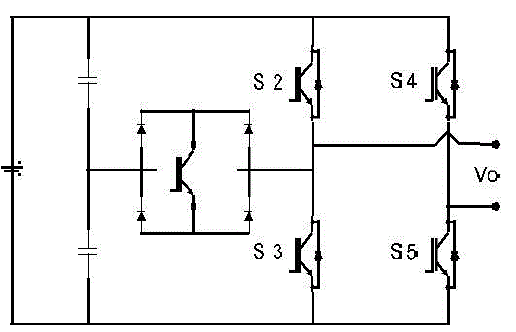
| Transistor clamped inverter topology is being popular nowadays, because it gives increase output level by providing simple modification in the conventional H-bridge. It uses series stacked capacitors for different level and a transistor clamped circuit with H-bridge which comprises of four diodes and one IGBT switch. This configuration uses transistor clamped H-bridge (TCHB) as a power cell to generate 5-level output rather then 3-level as generated with conventional H-bridge [12-14]. This topology is also classified in two groups based on balanced and unbalanced DC source as in cascaded H-bridge topology. 1. Symmetric Transistor Clamped Cascaded H-bridge Multilevel Inverter: Conventional TCHBs are itself called as Symmetric Transistor Clamped Cascaded Multilevel Inverter (SCMLI). It is formed by the series connection of two or more single-phase H-bridge inverters [15]. Each H-bridge comprises of two same voltage sources, where the line-line voltage is the inverter output. Therefore, a single H-bridge (power cell) can generate five different voltage levels. Fig. 3 shows the basic TCHB power cells with an additional bidirectional switch connected between the first leg of H-bridge and mid-point of series connected capacitor. It provides five level output (+Vdc, +1/2Vdc, 0) based on the switching combination given in Table I. The number of power cells required is mainly depending on operating voltage. |
 |
| In general, the maximum levels in the phase and line voltages of the proposed inverter, based on NC cells, are given by the equation given below: |
CONTROL TECHNIQUE OF MHPP |
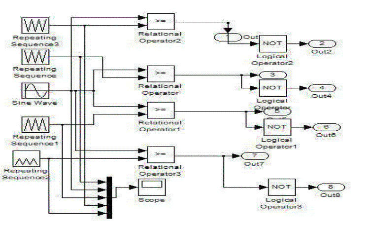
| It is generally seen that the performance of any inverter, with any switching scheme can be related to the harmonic contents of its output voltage. There are many modulation techniques reported in literature [16-17] for cascaded multilevel inverter. But the popularly used modulation method is the multicarrier pulse width modulation (PWM) technique. PWM uses high frequency for their operation. PWM technique is of three types: Phase Opposition Disposition (POD) and Alternate Phase Opposition Disposition (APOD), Phase Disposition (PD). Phase Disposition (PD) PWM technique is the generally used method in cascaded multilevel inverter as it gives a reduced total harmonic distortion (THD) .This paper focuses on a PDPWM technique. In this paper, Phase Disposition Pulse Width Modulation (PDPWM) is proposed as shown in Fig. 4, which uses the conventional sinusoidal reference signal and the carrier signals with fixed frequency [18]. To implement an mlevel inverter, (m-1) carriers are used. There are four carriers with fixed frequency and with the same magnitudes. The carrier signals C1 to C4 have same frequency. The pulses are generated whenever the amplitude of the signal which is going to modulate is greater than that of the carrier signal. The number of switching per modulation cycle (t) in each level of the inverter is dependent on the carrier frequency for that level and the duration of time that the reference waveform dwells within the level’s corresponding time band. If the carrier frequency for all the levels is identical, the top and bottom levels will have more switching than the intermediate levels. In order to balance the switching action, the carrier frequency of each band is varied based on the time duration that the reference waveform dwells in the carrier band. Using the amplitude symmetry of the sine wave about the time axis, the band crossing times, where the reference waveform crosses from one band to adjacent band can be calculated. In cascade multilevel inverter, the eight gate pulses for the two H-bridge are given by comparing the reference signal with the eight carrier signals. The reference signal is taken as sinusoidal and the carrier signals C1-C4 as triangular. The carrier signals are compared with the reference signal using a comparator, four signals are produced. These signals are given as input to logic gate to produce five output signals. These signals are given to the five switches of the H-bridge of TCMLI to produce a five level output waveform. |
 |
SIMULATION RESULTS |
| The analysis of transistor clamped multilevel inverter is done and verified using computer simulation. Models of TCMLI are constructed in the MATLAB-Simulink software. A hybrid modulation strategy which combines sinusoidal reference wave and carrier waveform with fixed frequency is employed. By the help of controller, 5-level output voltage and harmonic analysis are obtained which is shown in Fig. 5 and Fig. 6. In the simulation switching frequency used is 1 KHz. |
 |
CONCLUSION |
| In this paper, a novel micro-hydro power plant is presented, including capabilities of independently and simultaneously controls the AC power of inverter with load. A detailed model and a control scheme of the MHPP system are proposed. Digital simulation studies demonstrate the effectiveness of the proposed developments. The fast response of the PES and the good performance of its control allow full advantage of the MHPP as a DG system. The proposed MLI model provides efficient and quality output for any load by using variable speed of its turbine. |
References |
|