Keywords
|
| Cylindrical tank, Level, NI ELVIS, MATLAB, PID Controller |
INTRODUCTION
|
| Controlling of Level process is considered as an important role in process industries. Therefore, to control such process PID controllers comes into picture. A PID control loop feedback mechanism is to control the error i.e. the deviation from the process variable and the required set point [2]. Manipulated variable is used to accomplish the process of reducing the errors to get the desired set point. A PID is also known as Three term controller due to the involvement of three separate constant parameters (Proportional, Integral, Derivative values).Response of the process can be examined by the degree of overshoot and oscillation. |
| The plant is controlled by a control input u(t), which can be expressed as |
 |
| Where, |
 |
| The term kp has the adjustment of controlled output, ki produces the zero steady state and kd provides rapid system response. Present error e(t), past error de(t)/dt and anticipated error ∫e(t) dt reduction makes the controller as “Bread and Butter” for control Engineers. Performance Specification like marginal stability, Transient response and bandwidth are enhanced using tuning of PID controller. |
| MATLAB is a matrix Laboratory which is used by all sorts of Engineers. It helps to research and visualize ideas and get together around different field .It provides ease to user by offering graphical representation in programming. |
| NI ELVIS ( Educational Laboratory Virtual Instrumentation Suite) is a hands-on design and prototyping platform that integrating the 12 most commonly used instrument. It connects Pc through USB connection, provide quick and easy acquisition and display of measurement. |
| At first, the open loop response values for the cylindrical tank system are taken.NI ELVIS is used to interface the real time system to the PC. The level transmitter output of (4-20)mA is converted to voltage by invoking a resistor and the value is given to ELVIS & then to PC. The acquired values are tabulated and graph is obtained. From the response between level and time, the transfer function parameters (K, td,ïÃÂô) are determined using SK method. For the derived |
| transfer function, the PID tuning parameters (Kp, Ki, Kd) are calculated and it is applied to various tuning methods. The closed loop response can be obtained by simulation process using calculated values. In the Simulation process, the values are passed to PID controller with the help of MATLAB software. Based on the process output, the time domain specifications (Rise time, Peak time, Peak overshoot and Settling time) and error criteria values (ITAE, IAE, ISE, MSE) are encountered. On comparing the above specified characteristics which is shown in the tabulations below, the best controller for the real time cylindrical tank level process is found. |
RELATED WORK
|
| The procedure of the work is analysed and documented below |
| ïÃâ÷ Interfacing of real time cylindrical tank with PC and NI ELVIS |
| ïÃâ÷ Observation of change in level value with respect to time |
| ïÃâ÷ Analysis of readings and determination of the system function |
| ïÃâ÷ Simulation of diverse tuning methods which is invoked in the MATLAB software |
| ïÃâ÷ Analysis of the characteristics of process interms of time domain specifications and Performance error criteria |
| ïÃâ÷ Conclusion of best suitable controller for the cylindrical level system. |
EXPERIMENTAL SETUP
|
| It consists of process tank, level transmitter, pump, I/P converter, Computer, Rotameter. The inlet range of the rotameter is (10-100) LPH which pass the flow to the storage tank with the help of centrifugal pump of 0.5HP causing the level to increase. The level of the tank is sensed by two wire sensor and transmitted to the controller (PC).The electronic range of the level transmitter is (0-90) cm and output is (4-20) mA. A control valve of pneumatic actuator with air to close type is used, which acts based on the I/P converter pressure value of (3-15) psi achieves the level control. |
 |
| OPEN LOOP RESPONSE (TWO POINT METHOD): |
| In the level process to determine the transfer function the readings are taken between level and time and it is enforced in SK method. The SK method formula is |
| td=1.3t35.3-0.29t85.3 |
| tp=0.67(t85.3-t35.3) |
| REAL TIME READINGS FOR LEVEL PROCESS: |
 |
DETERMINATION OF TRANSFER FUNCTION
|
| Transfer function defines the relationship between input and output parameters of level process. Generally the transfer function is expressed as |
 |
| Where |
| Kp is the gain of the process |
| td is the dead time and |
| τ is the time constant of the system |
| From the above readings and the graph plotted below, the parameters are calculated using SK method which provides the transfer function of |
 |
TUNING METHODS
|
Ziegler Nichol’s Method:
|
| It is introduced in the year 1940s, which made a large strike in the acceptance of PID feedback controls by control Engineers. Using ZN method, PID loops are used for practical applications to improvise performance. This methods requires Ku(ultimate gain) and Pu (ultimate time period). To find the values bode and root locus are needed, which can be found by coding in a M-File. It provides a table to find kp,ki and kd values by substituting the determined Ku and Pu values. |
Modified Ziegler Nichol’s Method:
|
| It is the upgraded version of Ziegler Nichol’s Method and it provides the better response with good stability. This provides the smaller overshoot and reduces the undesirable oscillation |
Tyreus-Luyben Method:
|
| It starts with a low value of Kp and perturb the system input to an oscillation in output. By increasing the Kp value, sustained oscillation is observed. Ku used is the smallest value of Kp, which achieves oscillation and Pu is the period of oscillation at Ku. |
Chien Hrones Reswick Method:
|
| It focuses on two factors Set point Tracking and Disturbance Rejection, which further has a division of No overshoot and some (20%) overshoot[1]. Based on the application, whether the desired level is to be reached or the noise to be eliminated, the factors are selected. |
Internal Model Control:
|
| IMC is developed by Garcia and Morari in the year 1980.The controller depends on two element and they are complexity of the model and performance requirements given by the designer. |
MINIMUM INTEGRAL ERROR CRITERIA
|
| The criteria are used to figure out the best controller for various methods. They are |
| i) ITAE : Integral Time Absolute Error |
| This error criterion produces a system based on the time .It has sluggish response in the initial stage and settle it quickly by avoiding oscillations. |
 |
| ii) IAE : Integral Absolute Error |
| It does not weight any errors but provides the less sustained oscillation. |
 |
| iii) ISE: Integral Square error |
| It provides the better response for larger errors because the square of larger error results in further larger value. So it responds quickly for larger errors and took larger time period for smaller errors.[3] |
 |
| iv) MSE: Mean Square Error: |
| It is mostly used for defining the natural energy of a signal and it’s popularity is due to simple usage even it can be used in signal processing. |
 |
RESULTS & COMPARISON
|
FIGURE 1
|
(A) PID values for different tuning methods
|
| Using various controller tuning methods and with the help of their respective formula, the tuning parameters are found and tabulated below |
 |
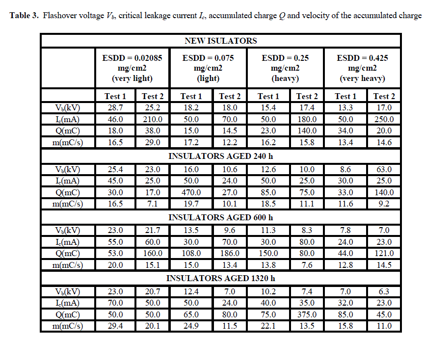
( B) Time Domain Specifications
|
| From the simulated response representing the real time level process, their characteristics are determined and listed out in a tabulation below |
 |
(C) Performance Error Criteria
|
| To find the best controller, the error reduction standards are necessary. Therefore, ITAE,IAE,ISE and MSE values are shown below in a tabulation |
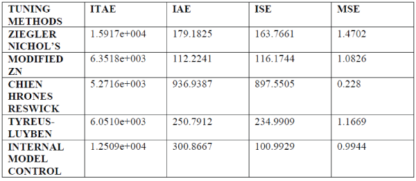 |
| In the above figure 1, (A) is the PID values for various tuning methods are calculated and the characteristics of the process when it is fed into the system are listed in (B) and (C) as time domain specifications and error criteria. |
GRAPHS
|
FIGURE 2
|
(A) Open loop response
|
| The response taken from the level transmitter between level and time is plotted below |
 |
(B) Closed loop response of various tuning Methods
|
| Closed loop response using different PID tuning methods are plotted in a single graph for the ease of comparison |
 |
| In figure 2, the calculated values are shown in the form of responses, where (A) is the open loop response used for the determination of transfer function, which is needed for the process differentiation. (B) is the outcome of the system function with different tuning techniques and it is also used for comparison that increases the chance of finding the best controller action for the given system. |
CONCLUSION
|
| From the above analysis of the real time cylindrical tank process, several criteria’s are established. Based on certain feature, the best controller has to be observed. |
| Depending on time domain specifications and minimum error integral criteria, the controller which possesses the best characteristic is ZIEGLER NICHOL’S METHOD. Therefore, ZN is suitable for the level process |
 |
References
|
- Mohammad Shahrokhi and AlirezaZomorrodi, “Comparison of PID Controller Tuning Methods “, 2012
- Tuning Of Controllers for Non Linear Process Using Intelligent Techniques D.Mercy1, September 2013 S.M.Girirajkumar IJAREEIE Vol. 2, Issue 9, September 2013
- K.Karthik Krishnan and G.karpagam,”Comparison of PID controller Tuning Techniques for a FOPTD system”, IJCET, Vol 4, Issue 4, Aug 2014
- Ogata K.”Modern Control Engineering”, 1997, 3rd edition, Prentice Hall
|