ISSN ONLINE(2319-8753)PRINT(2347-6710)
ISSN ONLINE(2319-8753)PRINT(2347-6710)
Santhosh Kumar D K 1, Prof Aravind Kumar 2,C haitra C R3
|
| Related article at Pubmed, Scholar Google |
Visit for more related articles at International Journal of Innovative Research in Science, Engineering and Technology
Medium Access control(MAC) protocol is the most widely used protocol for Adhoc networks. However, in practice, deafness, hidden-terminal, and exposed terminal problems are exaggerated with directional antennas, and they cause the degradation of the overall network performance. Although there are several random-access-based medium-access control (MAC) protocols being proposed in the literature for networks with directional antennas, the deafness, hidden-terminal, and exposed terminal problems have yet to be fully solved. In this paper, we present a new MAC protocol called the DSDMAC Protocol for wireless multi hop Ad Hoc Networks using Directional Antennas. Different from existing protocols, the DSDMAC protocol relies on the dualsensing strategy to identify deafness, resolve the hidden-terminal problem, and avoid unnecessary blocking. The integrity of the DSDMAC protocol is verified and validated using NS-2, which is a formal protocol network simulation tool. We further develop a animation scenario to quantify the performance of the DSDMAC protocol and conduct extensive simulations, which verify the accuracy of the analysis. The protocol verification, analysis, and simulation results show the robustness and superior performance of the DSDMAC protocol, which can achieve a much higher network throughput and lower delay utilizing the spatial multiplexing gain of the directional antennas. The results presented in this paper show that the proposed DSDMAC protocol can substantially outperform the state-of-the-art protocols.
Keywords |
| Access protocols, ad hoc networks, computer simulation, directional antennas, multiple access, system analysis and design. |
INTRODUCTION |
| USING directional antennas, a higher antenna gain can be achieved, which results in a higher data rate, a larger transmission range, and/or a less transmission power. There are many applications using directional antennas. Vehicular networks, for example, are a natural application since the vehicular traffic usually follows a straight line. Millimeter-wave communications also use directional antenna to combat severe path loss [2]. When used in a network, directional antennas can reduce the number of blocked nodes and achieve higher spatial reuse. However, effective medium-access control (MAC) protocols that support the directional antenna face several challenges. In particular, the hidden-terminal, exposed-terminal, and deafness problems severely affect network performance. |
| Different from the situation with omnidirectional antennas, hidden terminals in networks with directional antennas are located near the source node, as they may not hear the source’s transmissions; therefore, they may initiate transmissions, which lead to collisions. Deafness, on the other hand, occurs when a targeted destination does not reply when it is transmitting or receiving at a different direction. If it is not handled, failed transmissions due to deafness might be treated as collisions by the source node. Even worse, the source node may conclude that the destination node is unreachable. Using directional antennas in ad hoc networks poses challenging problems for MAC protocol design. The main contributions of this paper are of threefold: First, we propose a dual-sensing directional MAC protocol (DSDMAC) for networks with directional antennas. The protocol helps to improve the throughput and delay performance of the wireless networks by minimizing the negative effect of the hidden-terminal, exposed-terminal, and deafness problems. The protocol uses a noninterfering out-of-band busy-tone signal combined with sensing the activity on the actual data channel to identify deafness situations and to avoid unnecessary blocking. In addition, the protocol avoids the asymmetry-in-gain problem introduced by other solutions. Second, the integrity of the DSDMAC protocol is simulated using NS-2, which is a formal protocol simulation tool. Finally, a framework for throughput and delay analysis of wireless ad hoc networks using directional antennas is presented. The simulation results, showing the advantages of applying the DSDMAC protocol, which can improve the throughput efficiency of the network. The rest of this paper is organized as follows: Section II reviews the related work. In Section III, we define the MAC design issues using directional antennas and the system model. The DSDMAC is introduced in Section IV, Sections followed by V simulation results and protocol validation VI , respectively. Concluding remarks are given in Section VII. |
II.RELATED WORK |
| Random-access-based MAC protocol design and analysis for ad hoc networks has attracted extensive research [3]–[6]. We focus on those considering directional antenna, which can be classified into the nonbusy-tone-based protocols and the busy-tonebased protocols, as discussed here. |
A. Nonbusy-Tone-Based Protocols |
| The directional MAC (DMAC) proposed in [7] is one of the earliest protocols that support directional antenna. Based on a modified 802.11 MAC protocol, DMAC uses a per-sector blocking mechanism to block a sector once it senses a request-to-send (RTS) or clear-to-send (CTS) packet. A node can transmit its RTS packet in an omnidirectional fashion when none of its sectors is blocked; otherwise, it beams toward its destination. The omnidirectional transmissions may cause unnecessary blocking, and the protocol requires knowledge of neighbors’ locations. In [8], it is suggested that RTS/CTS packets be exchanged in an omnidirectional fashion (ORTS/OCTS) using all available sectors. After a successful ORTS/OCTS handshake, the data and Acknowledgment (ACK) are transmitted in the directions from which the OCTS/ORTS are received at the maximum power. The protocol is efficient in minimizing the hidden-terminal problem. However, it creates a severer exposed-terminal problem and cannot handle the deafness problem. In [9], a multihop RTS MAC (MMAC) protocol is proposed where all packets including RTS/CTS should use directional transmission (DRTS/DCTS). Nodes, however, may listen in an omnidirectional mode while they are idle. The deafness problem still exists as not all neighboring nodes can receive the DRTS and DCTS. The Directional Virtual Carrier Sensing protocol was proposed by in [10], which assumed a steerable antenna system to point at any specified direction. Each node maintains a list of neighbors and their directions based on the address of arrival (AoA) of any sensed signal. The AoA information is used to directly beam RTS packets to their destinations. If no location information exists, the RTS packets are omnidirectionally transmitted. A directional version of the network allocation vector is maintained for channel reservation. The protocol handles some basic functions required to support the directional antenna, and it cannot handle the hiddenterminal and deafness problems. The protocols in [11] and [12] suggested a circular directional RTS in which an RTS packet has to be transmitted multiple times in each direction. This helps to identify the location of the source node by its intended destination who replies a CTS packet at the direction of the source. Sending the RTS packet at all possible directions helps to notify the neighbors about the intended communication. However, this would not eliminate the deafness problem. The protocols also require synchronization mechanisms and cause undesired waste of time. In addition, the previous RTS/CTS-based mechanisms cannot be used for multicasting and broadcasting [13]. |
B. Busy-Tone-Based Protocols |
| Using a busy tone to enhance the MAC protocol has been an active topic [13]–[18]. The tone-based DMAC (ToneDMAC) protocol proposed in [14] uses two separated channels, i.e., a data channel and a control channel. While the data channel is used to transmit the RTS/CTS/DATA/ACK packets, the control channel is used to transmit a busy-tone signal. A unique busy tone is assigned to each wireless node, and therefore, it can be identified, and each node should maintain a hash function for all Neighbors’ locations. When a source node has data to transmit, it transmits a directional RTS packet toward its destination immediately after sensing the medium at the intended direction. The destination node in response replies with a directional CTS packet back to the source node. The source and destination nodes continue with exchanging the actual data at the specified directions, and meanwhile, they omnidirectionally transmit a busy tone. If the source node detects a busy tone rather than receive a CTS packet, it then concludes a deafness situation. The protocol can identify some deafness situations; however, there are chances to miss the busy-tone signal from either or both the source and destination nodes, which do not guarantee a deafness-free protocol. In addition, to avoid the hidden-terminal problem, the busy-tone signal needs to be simultaneously transmitted as the RTS packet, and it also needs to be sensed before any other transmission. In [15], the busy-tone signal to be transmitted by the destination node toward the direction of the source node only is proposed. The communication first starts with a DRTS/DCTS packet exchange in a directional manner. The redundant busy-tone signal would serve as another way to inform other nodes of the ongoing transmission in case they missed the DCTS packet. However, the deafness problem, which degrades the performance of the protocol, has not been addressed. Dual-Busy-Tone Multiple Access with Directional Antennas (DBTMA/DA), which was proposed by Huang et al. [16], is a modified version of the Dual Busy-Tone Multiple Access (DBTMA) in [17] to accommodate the nodes with directional antennas. As in the original DBTMA, the DBTMA/DA uses two distinctive busy tones: a transmitter’s busy tone (BTt) and a receiver’s busy tone (BTr). The receiver turns on its BTr upon receiving the RTS packet, whereas the transmitter turns on its BTt upon receiving the CTS packet. Therefore, hidden terminals are notified after the CTS is being transmitted by the receiving node, leading to a large gap during which several collisions may occur. In summary, how to solve the deafness problem and minimize the hidden terminal and exposed terminal problems for MAC protocol design is still an open issue, which motivates us to propose the DSDMAC protocol. |
III PROBLEM DEFINATION AND SYSTEM MODEL |
| A. Hidden- and Exposed-Terminal Problem |
| Unlike the omnidirectional counterpart, in directional antenna networks, the hidden terminals are located close to the source node. Theoretically, all nodes that are located within the destination node’s coverage area and are away from the source node’s coverage area are hidden terminals. The shaded area Ah in Fig. 1(a) indicates the area at which hidden terminals may exist. Hidden terminals can severely degrade the network performance. Unfortunately, the standard RTS/CTS mechanism fails to completely solve the problem, as nodes in Ah may initiate transmissions during the time the source node transmits the RTS, as discussed in [1] and [19]. |
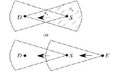 |
| Figure. 1. Directional antenna problems. (a) Hidden terminals. (b) Deafness |
| The exposed-terminal problem needs more attention in directional antenna networks. For example, if using ORTS and/or OCTS, nodes will unnecessarily block the sectors that can be used for concurrent transmissions; thus, it will waste the chance for higher spatial multiplexing gain, which defeats the purpose of using directional antenna. |
B. Deafness Problem |
| The deafness problem occurs when nodes use directional antennas in ad hoc networks. It happens when a source node fails to communicate with its intended destination, which is pointing at a different direction for transmitting or receiving. For example, node E in Fig. 1(b) is trying to communicate with node S whereas S is beamformed toward node D. As a result, node E will double its backoff time for retransmission, as it concludes that a collision has occurred. Even worse, when node E reaches the retry limit, it concludes that node S is unreachable. |
C. Asymmetry-in-Gain Problem |
| When using two different types of transmissions using the same antenna, e.g., a directional transmission for data packets and an omnidirectional transmission for control packets such as RTS/CTS, different transmission ranges lead to the asymmetry-in-gain problem. The transmission range of a directed signal and the transmission range of an omnidirectional radiated signal are not identical. As a result, the control packets omnidirectionally transmitted will not reach all the desired nodes. |
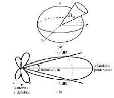 |
| Fig. 2. Antenna pattern. (a) Beam solid angle ΩA. (b) Antenna power |
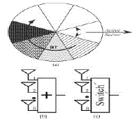 |
| Figure. 3. Directional antenna model. (a) Antenna sectors. (b) Omnidirectional function. (c) Selecting a specific sector.) |
D. Antenna Model |
| A directional antenna is thought of to be an isotropic antenna with a constant gain over a certain angle ΩA, as shown in Fig. 2(a). Since we are interested in using the antenna in the azimuth plane, the radiation pattern presented in Fig. 2(b) shows the main pattern attributes. The pattern consists of the main lobe at the direction of the maximum radiation intensity and other minor sidelobes. The half-power beamwidth (or simply beamwidth) is the angle between the edges in the main lobe that are down from the maximum gain |
E. Busy-Tone Signal |
| The busy-tone signal is a noninterfering sine-wave signal used to let other nodes be aware of an ongoing transmission. In this paper, two different patterns are used: a continuous pattern, which is referred to as BT1, and an ON/OFF pattern, which is referred to as BT2. The two patterns are shown in Fig. 4. BT1 and BT2 are used for different purposes, which will be discussed in more detail in the next section. When more than one busy-tone signals are constructively interfering with each other, a fall-back to a BT1 results. |
F. Effect of Mobility on MAC Protocols |
| Mobility in the wireless multihop ad hoc networks may affect both routing and MAC protocols. While the routing protocols need to deal with the change in connectivity among the wireless nodes, MAC protocols can only be affected if the time scale of the MAC frame transmission is similar to the time scale of the changes in the network. However, from the following example, the time to complete a MAC transaction is very short compared with the time scale of network connectivity changes due to mobility. Considering a vehicle traveling at a speed of 90 km/h in a highway, the time required to move the vehicle by 1 m is 40 ms, whereas a packet of a 12 000-bit payload requires only 2.2-ms transmission time by an IEEE 802.11 link with a data rate of 11 Mb/s. Accordingly, the mobility has a very limited impact on the MAC protocols, and it has a greater impact on the routing protocols, which are beyond the scope of this paper. |
IV. DUAL-SENSING DIRECTIONAL MEDIUM-ACCESS CONTROL PROTOCOL |
| The proposed DSDMAC protocol uses two well-separated wireless channels, i.e., a data channel and a busy-tone channel. The data channel carries the data packets and the RTS, CTS, and ACK packets on a specified direction (DRTS, DCTS, DDATA, and DACK). On the other hand, the busy-tone channel will be used to transmit a sine-wave busy-tone signal on all other directions. Only the source and destination nodes will transmit the busy-tone signal. The protocol assumes that the directions of all reachable destinations or forwarders are predetermined (during the node discovery period for example). |
A. Transmitting and Receiving With DRTS/DCTS |
| When the link layer of a wireless node receives data packets from its higher layer, it senses the activity on the data channel at the specified direction. If the specified sector is not blocked, the data channel is idle, and no BT1 is present, it immediately transmits a DRTS packet and turns on its BT1 signal at all other directions. In case a BT1 was sensed, other nodes should postpone any DRTS until BT1 disappears. Otherwise, the source node waits until the tagged sector is unblocked and becomes idle for the period of a distributed interframe space (DIFS). It then generates a random backoff interval before transmitting its DRTS packet. The backoff interval is randomly chosen between 0 and CW - 1, where CW is the initial contention window size. The backoff counter is always frozen whenever the node senses an activity on the data channels at the specified direction or whenever the sector at the specified direction is blocked (e.g., by DRTS/DCTS from other nodes). Once the backoff counter reaches zero, the node transmits its DRTS packet at the specified direction and turns on its BT1 signal over all other directions. The source node should change the BT1 to BT2 after finishing the DRTS packet transmission plus an SIFS duration. We will discuss the reason for the BT switching shortly. BT1 is used to avoid the hidden-terminal problem. Because DRTS cannot be sensed by the nodes in the hidden terminal area (see Ah in Fig. 1), these nodes can avoid initiating a new DRTS when they sense the BT1. BT1 can be turned off after the DRTS plus an SIFS because the nodes in Ah can sense the CTS to avoid collision. |
 |
| Figure 4. Busy-tone signal patterns |
| Once the source node successfully receives the DCTS, it directionally transmits the data packet. After that, if the source node does not receive a DACK packet within a specified ACK–timeout interval or it detects a transmission of a different packet, it reschedules the transmission of the data packet for a later time and doubles its backoff CW main lobes. Therefore, the probability of finding wireless nodes within the side lobes of the antenna is very small and can be ignored. The antenna has a constant gain within the beam width and zero outside. To cover all directions, we use S × Θ ≥ 2π, where S is the number of antenna sectors and Θ is the beam width of a single antenna sector, as shown in Fig. 3(a). Sectors can be simultaneously used to provide an omnidirectional receiving function, as shown in Fig. 3(b), or they can be individually switched for a specific direction, as shown in Fig. 3(c). An antenna controller is assumed. The controller keeps track of the directions from which a maximum signal power is received. It then informs the higherlayers about the sector of the received signal. The switching within the antenna controller can be achieved by using very fast analog CMOS multiplexers/demultiplexers, which have a transition time of less than 217 ns (e.g., ADG5408/ADG5409, four-/ eight-channel multiplexers). This transition time is less than the signal propagation delay. Therefore, the short interframe space (SIFS) defined in the 802.11 standard is long enough for the antenna being switched between transmitting and receiving modes. Data packets are transmitted using one sector, and the busy-tone signal may be rotationally transmitted one sector at a time over all available (nonblocked) sectors. |
 |
| Figure. 5. DNAV setting. |
B. DNAV Mechanism |
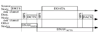
| When a node receives a valid DRTS packet, it should set its per sector directional network allocation vector (DNAV) timers. It also should block all of its sectors for a period with a duration of SIFS + DCTS, as shown in Fig. 5. We call this time DNAVDRTS time. Unless a DCTS packet is received, the node should unblock its antenna sectors when the DNAVDRTS timer is expired. If a DCTS packet is received, then only the receiving sector and the sector from which a previously DRTS packet is received (if applicable) should remain blocked for a period with a duration of 2 × SIFS + DDATA + DACK, so the node will not initiate any transmissions to interfere the ongoing transmission. We call this time DNAVDCTS time, as shown in Fig. 5. Using this DNAV design, we can minimize the exposed-terminal problem without increasing the collision probability. |
C. Case Study and State Transitions of DSDMAC |
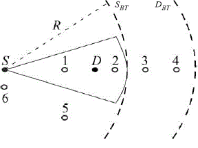
| To further illustrate how the DSDMAC meets its design goal, we use an example with the network configuration shown in Fig. 6. The source and destination nodes (S and D) are marked with solid dots. Nodes 1, 2, 3, and 4 are located on the same line connecting node S and node D. Nodes 5 and 6 are located at different directions. The dashed curve SBT marks the circular region of node S’s busy-tone signal range with a radius of R. Likewise, the dashed curve DBT marks the circular range of node D’s busy-tone signal. The message exchanges among these nodes are shown in Fig. 7, where the arrow within each packet indicates the direction used to transmit that packet. As shown in Fig. 6, node S waits until nodes 1 and 2 finish their communication. Meanwhile, nodes 3 and 4 may independently start their communication because the direction from node 3 to node 4 is not blocked. When node S senses no BT1 in the busy-tone channel and no new activities in the data channel, and its corresponding antenna sector toward D is not blocked, it starts its transmission to node D after a backoff period. Any further transmission from node 1 to node 2 must be deferred until node S finishes. However, node 5 can independently start its transmission toward node 2 because the direction from node 5 to node 2 is not blocked. As a hidden-terminal, node 6 will be blocked from transmission while it hears the BT1 from S, and it will then receive D’s DCTS and avoid collisions. |
 |
| Figure. 6. Case study |
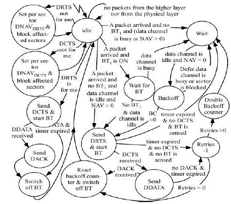
| The state transition diagram for the DSDMAC protocol is shown in Fig. 7. Although the states are self-explanatory, the following highlights the most important states, which are different from the IEEE 802.11 MAC protocol. The system is initially in its idle state until a packet arrives from the higher layers or a packet arrives from another node. When a packet arrives from the higher layers, there is no new activity in the data channel, no BT1 is sensed, and the corresponding antenna sector is not blocked, the system moves to the “Send DRTS & start BT” state and sets a timer to wait for the DCTS. Otherwise, the system moves to the “Wait” state until the channels become idle and the sector is unblocked; then, it moves to the “Backoff” state. |
 |
| Figure. 7. DSDMAC system state transition diagram |
| In case the timer expired without receiving a DCTS packet and a BT2 signal is presented, the system skips the “Double backoff counter” state, as it concludes that its destination might be busy toward other directions. In this case, the system will directly go to the “Wait” state. This transition helps the DSDMAC protocol to avoid the deafness problem. Deafness situations are also likely occurring if node 3 misses node 2’s CTS. The MMAC has also failed the test. The omnidirectional reception of the RTS packets, as stated by the protocol, will block node 6 from receiving node 5’s RTS when node 1 transmits toward node 2. In addition, the deafness situation occurs when node 3tries to send a packet to node 2 while node 2 is receiving from node 1. The ToneDMAC, on the other hand, shows good results on DMAC protocol can block node 5 from transmission when node 1 or node 3 starts a transmission to node 2. handling the blocking problem. However, according to the discussion in Section II, deafness situations are not completely prevented from transmission at the presence of the BTr signal. Deafness, however, was not reported. Finally, the validation results show that DSDMAC can handle both deafness and blocking as expected, and thus, it outperforms the other protocols. Next, we develop an analytical framework to quantify the protocol eliminated. The DBTMA/DA protocol is vulnerable to the blocking problem since a source node is omnidirectionally transmitting the RTS/CTS in the performance. |
V SIMULATION RESULTS |
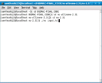 |
| Figure 8: commands needed use for terminal in linux fedora 9 to get the simulation results NS-2 |
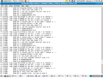 |
| Figure 9: Trace Results |
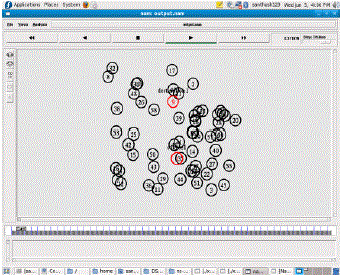 |
| Figure 10: Initial animation Scenario in network Animator of NS-2 |
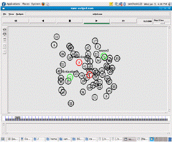 |
| Figure 11: communication between two nodes animation Scenario in network Animator of NS-2 |
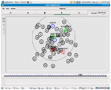 |
| Figure 12: Omni directional Busy tone signaling. |
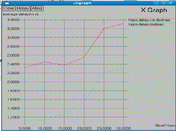 |
| Figure 13: average throughput in MBPS |
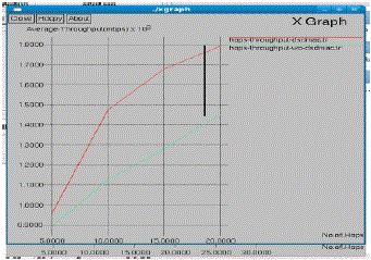 |
| Figure 14 :Average Hop Delay |
VI. PERFORMANCE EVALUATION |
| when the node density is getting higher, our proposed protocol can have even higher performance gain, as our protocol is the only one not affected by the blocking and deafness problems With the proposed DSDMAC, the delay can also be improved by increasing the number of antenna sectors. Fig. 13 shows the analytical confidence intervals of the simulation results. First, the accuracy of the analysis is validated by the simulation. Second, the results show that, with DSDMAC, more antenna sectors per node can result in a higher throughput. This is attributed to the reduction in the collision probabilities when more antenna sectors are used, as shown in Fig. 12. In addition, given the DSDMAC protocol can appropriately deal with the deafness, hidden-terminal, and exposed terminal problems, much higher throughput can be achieved in a dense network due to the spatial multiplexing gain by using the directional antennas. As shown in Fig. 14, when the node density figure shows that, in addition to the higher throughput, a smaller MAC delay can be achieved using DSDMAC with directional antennas. With 50 nodes per hop, while the average delay versus the average number of nodes using one, four, eight, and 16 antenna sectors. |
VII. CONCLUSION |
| In this paper, we have proposed a new MAC protocol called DSDMAC for wireless multihop ad hoc networks using directional antennas. The new protocol differs from the existing protocols by relying on the dualsensing machanisum to identify deafness, resolve the hidden-terminal problem, Deafness and avoid unnecessary blocking. The integrity of the DSDMAC has been verified using a formal protocol simulation tool called NS-2. NS- 2 results have shown that the DSDMAC protocol outperforms the existing protocols. We have also presented the Adhoc network using NS-2 network Animator, which has been verified by simulation. The simulation results have shown that applying the DSDMAC protocol can greatly improve the performance of wireless networks using directional antennas |
References |
|