International Journal of Innovative Research in Science, Engineering and Technology
ISSN ONLINE(2319-8753)PRINT(2347-6710)
ISSN ONLINE(2319-8753)PRINT(2347-6710)
A. Raveendra1,Dr. B. V. R. Ravi Kumar2 Dr.A.Sivakumar3 N.santhosh4
|
| Related article at Pubmed, Scholar Google |
Visit for more related articles at International Journal of Innovative Research in Science, Engineering and Technology
The present work aims to evaluate the effect of Gas Tungsten Arc Welding process parameters on the depth of penetration of the given specimen. In this study, TIG welding parameters influence on weldability of 5052 aluminium alloy specimens with dimension of 100mm long x 50mmwide x 2.5mmthick is investigated. The welding parameters such as arc voltage, welding current, welding speed, gas flow rate and heat input are taken into account which influence the depth of penetration measured after welding.
Keywords |
| AA5052, Arc voltage, Welding current, Gas flow rate, Heat Input, Welding speed. |
INTRODUCTION |
| TIG welding was demonstrated first by Russell Meredith in 1930 during second world war for welding aluminium and magnesium in aircraft industry [1]. Welding technology has obtained access virtually to every branch of manufacturing; to name a few, ships, rail road equipments, building construction, boilers, launch vehicles, pipelines, nuclear power plants, aircrafts, automobiles, pipelines. Welding technology needs constant upgrading and with the widespread applications of welding [2]. Welding is a fabrication or sculptural process that joins materials, usually metals, or thermoplastics, by causing coalescence. This is often done by melting the work pieces and adding a filler material to form a pool of molten material (the weld pool) that cools to become a strong joint, with pressure sometimes used in conjunction with heat, or by itself, to produce the weld. The important process variables in manual arc welding are: welding current, arc voltage, welding speed. The effects of these process variables are determined through their effects on weld bead penetration. Many efforts have been made to develop a mathematical model to study these relationships and best way to solve this problem is by using experimental model. Investigation into the relationship between the welding process parameters and bead geometry began in the mid 1900s and regression analysis was applied to welding geometry research by Lee and Raveendra [3, 4]. |
| The weld quality was strongly characterized by weld bead geometry because the weld pool geometry plays an important role in determining mechanical properties of weld [3-5]. The heat affected zone influenced with the increment of heat input due to increased welding current. The width of heat affected zone increases due to low heat input [11]. The weld bead geometry of weld repaired aluminium alloy was similar as cast aluminium alloy in appearance but different in micro-structure [12].The relation between welding parameters and weld bead geometry was investigated in gas metal arc welding process which results as greatest effect of welding current on weld bead geometry. If welding speed decreases beyond an optimum value, depth of penetration decreases due to the pressure of electric arc on weld pool [13]. Heat input parameter influence the cooling rate, weld bead size and mechanical properties of weld [14]. Less depth of penetration was obtained for low gun angle because of less pre-heating of base metal [15]. Aluminium alloy have many applications in different fields because of good mechanical properties and corrosion resistance. |
| Literature Survey: Penetration is considered as one of the most important properties of a weld,since it determines the stress carrying capacity of the welded joint [16].It represents the maximum linear distance below the original surface of the plate and perpendicular to a given cross section.Though Tsegelsy[17] states that thedepth of penetration depends on the amount of heat given up by the arc which is dependent upon the arc current,it is generally recognized that penetration is influenced by current,voltage and welding speed[16,17].It has also been reported[17] that the diameter of electrode affects the penetration and other parameters of the weld bead. |
 |
A. Welding Current and Arc voltage |
| It controls the melting rate of the electrode and thereby the weld deposition rate. It also controls the depth of penetration and thereby the extent of dilution of the weld metal by the base metal. Arc voltage, also called welding voltage, means the electrical potential difference between the electrode wire tip and the surface of the molten weld puddle. It hardly affects the electrode melting rate. |
B . Welding Speed and Heat input |
| Welding speed is the linear rate at which the arc moves with respect to plate along the weld joint. Welding speed generally conforms to a given combination of welding current and are voltage. If welding speed is more than required heat input to the joint decreases, less filler metal is deposited than required , Reinforcement height decreases’. If welding speed is slow ,heat input rate increases, Weld width increases and reinforcement height also increases more convexity [9]. |
C. Gas flow rate |
| Argan is the most used GTAW shilding gas. Argon is used in welding of carbon and stainless steels and low thickness aluminium alloys components. Gas flow rate influence the welding speed and improves process tolerance. |
| Heat input rate=60VI/v J/mm |
| V=arc voltage in volts |
| I=welding current in ampere, |
| v =speed of welding in mm/min. |
III. MATERIALS AND METHODOLOGY |
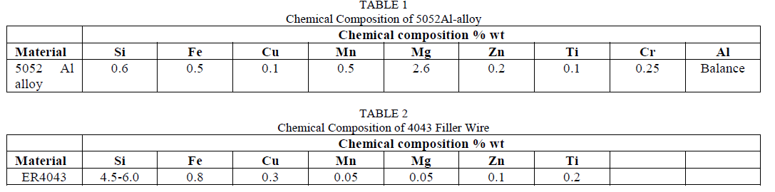
| The Experimental material is selected as 5052 Al-alloy of 100mmlong x 50mmwide x 2.5 mm thickness, which is welded by TIG welding after surface preparation. The chemical composition of 5052 Al alloy is shown in Table 1 |
 |
| Aluminium alloy 5052 contains 2.5% magnesium & 0.25% chromium. It has good workability, medium static strength, high fatigue strength, good weldability, and very good corrosion resistance, especially in marine atmospheres. It also has the low density and excellent thermal conductivity common to all aluminium alloys. It is commonly used in sheet, plate and tube form. |
| The filler wires used to transfer the extra material to fill the gap between the joints of same composition of base metal. There are different types of filler wires such as , 5356, 4043,and 5654 available in the market on the basis of base metal compositions. In this experimental work, the filler wire of 4043 grade is selected for welding the 5052 Al- alloy specimens because of its good, similar physical, mechanical properties and chemical compositions for obtaining the best weld joint. The chemical composition of 4043 filler wire is shown in table 2. |
| 4043 aluminium filler materials are silicon-aluminium types for welding of 6052 and 6063 types; in some cases, other aluminiums are also welded with this type. Brazing of 1100 and 3003 can be accomplished with free flowing 4043 composition. The proper choice of aluminium filler metal mainly depends on the base metal properties to be achieved and Welding technique. Post weld cracking, corrosion resistance and behaviour under elevated temperature also need to be taken into consideration. Cracking usually can be minimized by choosing a filler metal alloy of higher alloy content then the base metal. |
IV. EXPERIMENTAL SETUP |
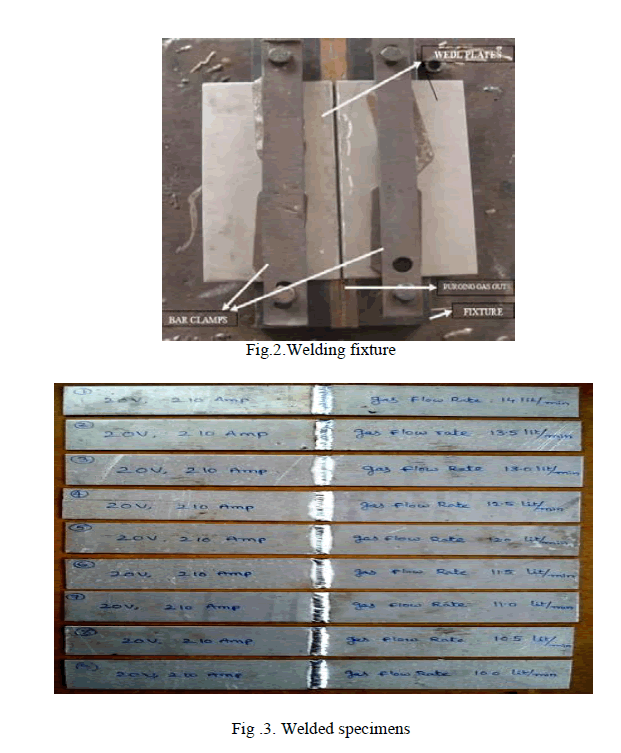
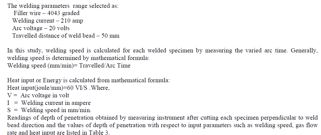
| In this experimental work TIG welding is used. TIG welding is the welding process of joining different materials with high quality weld bead by electric arc generation between electrode and work piece. TIG welding process is adopted to weld 5052 aluminium alloy with use of 4043 graded filler wire. Nine specimens of dimensions 100 mm long x 50 mm wide x 2.5 mm thick are prepared, then weld each two specimens and form nine number of butt weld joints, welded specimen is shown below in Figure 3: |
| Before welding, edges of the work pieces are suitably prepared. The edges are cleaned of dust using wire brush and cloths. Afterwards, the work pieces to be welded were positioned with respect to each other as shown in figure 2 and welding process was performed. |
 |
 |
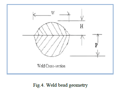 |
| W- Weld Width, P- Penetration, H- Reinforcement |
| During the welding process, Current = 210, AmpTerminal voltage = 20 V |
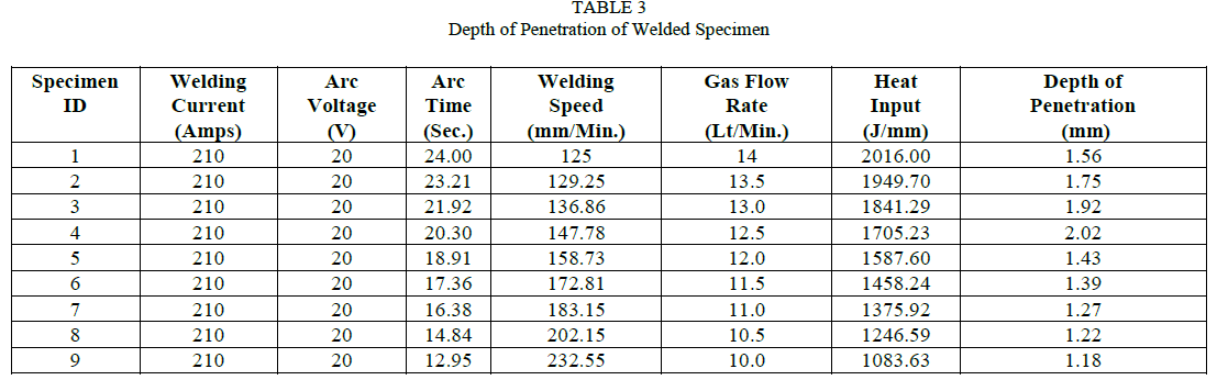
| Only Gas flow rate was varied during the welding. Welding speed was calculated for each welded specimen. Having finished the welding processes, in order to measure the depth of penetration, welds were cut perpendicular to the direction of welding on power hacksaw. Then with the help of measuring instrument, depth of penetration of welded specimens was measured. |
 |
V. RESULTS AND DISCUSSIONS |
| Depth of penetration measured from sectional cross cutting of weld beads through measuring instrument after cutting all the welded specimens perpendicular to the direction of welding are shown in the table 3 and variations in the penetration are analysed with the help of graph as shown in graph no. 1,2&3. The depth of penetration increases with increasing welding speed up to 147.78 mm/min which was optimum value to obtain maximum penetration, because it begins to decrease linearly after this point. Increasing the speed of travel and maintaining constant arc voltage and current increases penetration until an optimum speed is reached at which penetration is maximum. Increasing the speed beyond this optimum result in decreased penetration and maximum depth of penetration occurs at heat input rate of 1705.23J/mm. Greater the depth of penetration, better is the weldability. So, Optimum weld ability can be obtained with heat input rate as 1705.23J/mm. So it can be concluded from experimental analyses is that for the specimen 5052 Al-alloy grade of 100mm long x 50mm wide x 2.5 mm thickness ,optimum weldability can be achieved by considering the welding parameters as welding speed, 147.78 mm/min with current 210 Amp, arc voltage 20 V and gas flow rate 12.5Lt/mm. |
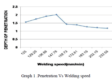
A. Effect of Welding Speed on Depth of Penetration |
| The evaluation of data of welding speed and depth of penetration which helps to analyse the variation in depth of penetration. Arc time is varied during the welding of 5052 Al-alloy specimens at constant voltage and current value of 20 volt and 210 amperes. It is clear from Figure 1 that describes the depth of penetration increases linearly by increasing welding speed until an optimum value which gives maximum penetration. After this optimum value, depth of penetration begins to decrease linearly. Therefore, maximum penetration of 2.02 mm is obtained for specimen 4 at welding speed of 147.78 mm/min. Graph1 |
 |
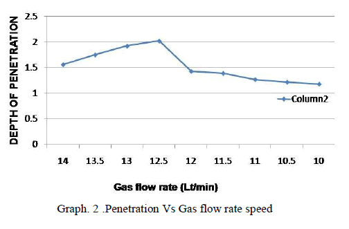
B. Effect of Gas Flow Rate on Depth of Penetration |
| The graph2 clearly describe that as increasing gas flow rate, the depth of penetration increases until an optimum value which gives maximum depth of penetration. The depth of penetration begins to decrease linearly after that optimum value. Therefore, maximum penetration of 2.02 mm is obtained for specimen 4 at gas flow rate of 12.5 Lt/min |
 |
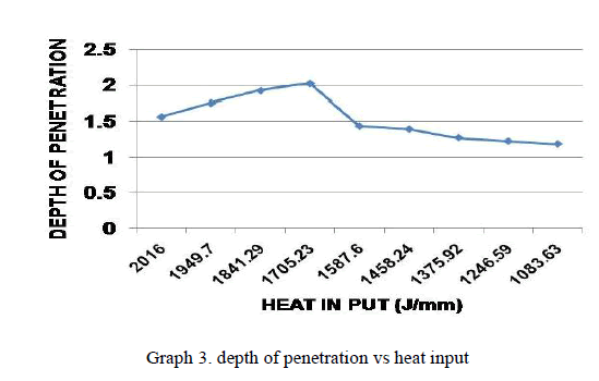
C. Effect of Heat Input on Depth of Penetration |
| The graph 3 drawn between heat input and depth of penetration shows that as increasing heat input, the depth of penetration increases until an optimum value which gives maximum depth of penetration. After that optimum value, depth of penetration begins to decrease linearly. Therefore, observe the maximum depth of penetration of 2.02 mm for specimen 4 at heat input of 1705.23J/mm. |
 |
VI CONCLUSION |
| Optimum parameter range for weldability of 5052 Al – alloy specimens with dimensions of 100mm x 50mm x 2.5 mm for arc voltage of 20 volt, current of 210 ampere, welding speed of 147.78 mm/min., gas flow rate of 12.5 Lt/min. and heat input of 1705.23 joule/mm. are carried out to be: |
| 1. Deep penetration of 2.02 mm is obtained for welding speed of 147.78 mm/min. |
| 2. Maximum depth of penetration is achieved at gas flow rate of 12. 5 Lt/min. and heat input of 1705.23 J/mm. |
| Hence, It can be concluded that as the welding speed increases at constant current and voltage, the depth of penetration will increase until an optimum value which shows maximum penetration. The depth of penetration will decrease when welding speed increases beyond the optimum value. |
References |
|