ISSN ONLINE(2319-8753)PRINT(2347-6710)
ISSN ONLINE(2319-8753)PRINT(2347-6710)
| PrashanthDevaraj, Prakash Rajendran, Maran P Department of Mechanical Engineering, Thiagarajar College of Engineering, Madurai, India |
| Related article at Pubmed, Scholar Google |
Visit for more related articles at International Journal of Innovative Research in Science, Engineering and Technology
This paper reports the observations made during the numerical simulation study of high Reynolds number flows in a bluff body combustor of gas turbine engines. The numerical results were first validated with the results studied experimentally at the University of Sydney and at Sandia National Laboratories and then analysed under different inlet conditions. The analysis involves a comparative study of effects of different flow conditions of the particular geometry. Effects of the inlet velocity, equivalence ratio and bluff body shape on the combustion efficiency (in terms of mass fraction of CO2) and exhaust gas temperature were examined. It was found that the flow field is characterized by high turbulence at the onset of the hollow cylindrical bluff body used in the study. The results also show that the exhaust gas temperature decreases first and then increases with the decrease of the velocity ratio. Furthermore, comparatively high temperatures can be maintained over the whole equivalence ratio range at a moderate velocity magnitude
Keywords |
| Combustor, Bluff body, non-premixed, Reynolds stress model |
INTRODUCTION |
| Ground-based or aero gas turbine applications incorporate flame holders in the form of bluff bodies or swirlers for a primary or secondary combustion in high speed reacting flows. These two methods are very prominent among combustion systems over a long time. Recent gas turbine combustors use a combination of the two for a more efficient combustion process. Researchers have been studying the effects of fluid flow inside a combustion chamber which is characterized by high turbulence caused by the wake formation. |
| In bluff body combustion, a non-streamlined body is placed in a high-speed flow which produces a recirculating zone in the wake region that allows the combustion products to settle in this region for continuously igniting the incoming flow of fuel and air from which the flame propagates into the free stream. Although a premixed combustion regime is becoming increasingly popular for industrial gas turbines because of their potential for very low NOx emissions, combustion in conventional aircraft gas turbines occurs predominantly in the non-premixed diffusion flame regime. In such devices, turbulent mixing exerts a dominant influence and better understanding necessarily requires an accurate prediction of the turbulent velocity field. Turbulent reacting flows form an important class of industrially relevant systems that are amenable to numerical simulations. With increased importance of pollutant control and process optimization, Computational Fluid Dynamics (CFD) can play a vital role in the design and development of environment-friendly chemical processes. Accurate prediction of these models and codes is performed on their validation with experimental data. CFD techniques need to contain sufficient description of the flow as well as reaction physics. |
| Turbulent combustion of gaseous fuels has been numerically investigated by many researchers for the past six decades using various turbulent models. Mare et al [1] observed that accurate description of the inlet section of the combustor plays a significant role in the prediction of temperature distribution over the flow region in a can-type model gas turbine combustor using numerical simulation technique. Khalil et al [2] suggested that swirl in the combustor will improve the performance with improved fuel mixture preparation prior to the ignition of fuel at higher operational pressures. Decreasing the equivalence ratio changes the flame shape [3] due to reduced flame speed such that the flame fronts overlap the convecting Kelvin–Helmholtz vortices along the shear layer. Ziani et al [4] compared the three turbulence model for non-premixed combustion and evaluated with the numerical results of the literature and experimental data. The evaluation resulted in the conclusion that the modified k- model is the most appropriate for simulating the non-premixed turbulence combustion. |
| The bluff body stabilized flames have found wide range of applications because of their relatively low pressure drop and simple geometry [5]. The combustion with a bluff body stabilized fame of gases fuel for both the premixed and non-premixed flame conditions have also been numerically and experimentally investigated by many researchers. Giacomazzi et al [6] studied the combustion in a bluff-body flame anchored in a straight channel and the corresponding results for both cold and reactive flows using eddy dissipation concept for a turbulence intensity of 3 to 4 % and an equivalence ratio of 0.65. The impact of increased reactant temperature on the dynamics of bluff-body stabilized premixed flows was investigated by Erickson et al [7]. |
| Vervisch [8] reviewed the use of numerics to understand and model non-premixed turbulent flames and first gave a rapid overview of non-premixed turbulent combustion modelling. Schefer et al [9] measured the velocity in a turbulent bluff-body stabilized methane flame. The flow configuration consisted of a 5.4-mm diameter fuel jet separated from an outer, annular-air flow by a 50-mm diameter bluff-body. Wana et al [10] investigated numerically and experimentally the effect of equivalence ratio on combustion characteristics of premixed hydrogen/air flame in a micro-combustor with a bluff body using Fluent 6.3. |
| CFD based on RANS equations has been widely developed and used to improve and reduce costs in aerodynamic design. LES is costlier and time consuming even though it is attractive for non-premixed combustion because unsteady large scale mixing between fuel, oxidizer and products is directly simulated, instead of being averaged with small scales as in RANS. Lysenko et al [11] numerically analysed the turbulent separated planar bluff-body flows using the state-of-the-art Open-FOAM and ANSYS FLUENT technologies, based on the conventional URANS approach. The results demonstrated minimum deviations between Open FOAM and FLUENT and agreed fairly well with the experimental data and other numerical solutions. |
| The main objective of the present work is to identify a correct model for a geometry under study and then analyse the effects of the various parameters on the overall efficiency of the system. |
TEST CASE DESCRIPTION AND NUMERICAL MODEL |
| A. Geometry and flow configuration |
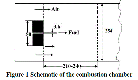
| The geometry of the combustion chamber is shown in Figure 1. The configuration used here is the bluff-body stabilized CH4 flame investigated experimentally at the Sandia National Laboratories and the University of Sydney documented in [12, 13]. It has an outer diameter of 50 mm with a concentric fuel jet of diameter of 3.6 mm. The complete burner assembly was housed in a cylindrical co-flow wind tunnel of diameter 254 mm. For the flame the fuel jet velocity was 118 m/s with a coflow velocity of 40 m/s. |
 |
B. Computational modelling |
| The modelling of the geometry was done using GAMBIT 2.4.6. Since the geometry is cylindrical without any swirler or tangential velocity inlet, the model can be assumed to be an axi-symmetric problem. The computational domain of the axi-symmetric model of the combustor with boundary conditions is shown in Figure 2. |
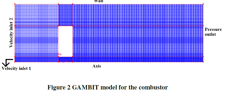 |
| A very fine mesh is imposed around the hollow cylindrical bluff body for precise measurements of the flow conditions. Zero velocity impermeability boundary conditions are specified at the bluff body walls. The boundary conditions are also presented in Figure 2. |
| The top edge has been taken as wall, the left edge as velocity inlet, the right edge as pressure outlet and the bottom edge as axis. The velocity inlet 1 is for the fuel inlet and the velocity inlet 2 is for the air inlet. A total of 97600 nodes were used for meshing the geometry. Map-type rectangular meshes with an interval size of 0.2 mm were used. |
| C. Numerical model validation |
| The simulations have been done using the commercial CFD package – FLUENT 14.0. CFD techniques consist of numerical solutions of mass, momentum and energy conservation. Solution to the CFD problems is obtained in two main stages. The model initially is divided into small control volumes called meshes in the first stage. Then the numerical solutions of mass, momentum and energy conservation equations are done. The diffusion and convection terms are discretized using the central and second-order upwind schemes, respectively. The SIMPLE algorithm is used for pressure-velocity coupling. Three turbulent models namely, the Renormalized group (RNG) k-(2 equations) model, the Shear-stress transport (SST) k- (2 equations) model and the Quadratic pressure-strain Reynolds Stress Model (RSM) have been solved and compared. |
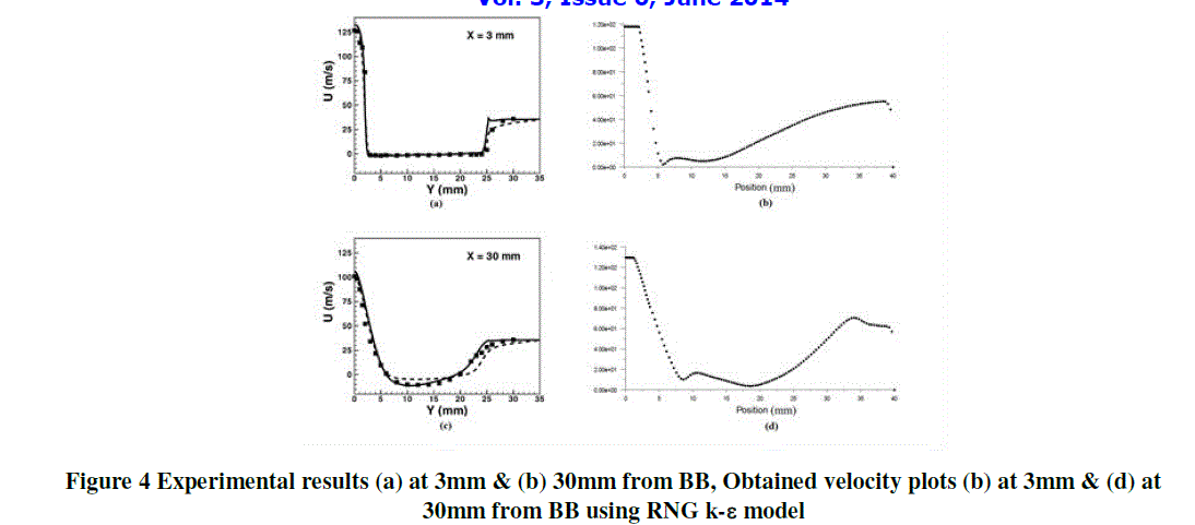
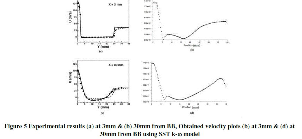
| In the geometry, the horizontal distance along the axial direction is taken as X and the vertical distance along the radial direction is taken as Y. The experimental velocity plots done in [12, 13] along the radial direction with an axial distance of 3mm and 30mm respectively from the bluff body has been shown in Figure 3. |
 |
| D. RNG k- ε model |
| The simplest “complete models” of turbulence are the two-equation models in which the solution of two separate transport equations allows the turbulent velocity and length scales to be independently determined. The RNG model has an additional term in its equation that significantly improves the accuracy for rapidly strained flows. The effect of swirl on turbulence is included in the RNG model, enhancing accuracy for swirling flows. The corresponding plots obtained using this model has been shown in Figure 4. |
 |
| E. SST k-ε model |
| The Wilcox model predicts free shear flow spreading rates that are in close agreement with measurements for far wakes, mixing layers, and plane, round, and radial jets, and is thus applicable to wall-bounded flows and free shear flows. The corresponding plots obtained using this model has been shown in Figure 5. |
 |
| F. Quadratic pressure strain RSM |
| Since the RSM accounts for the effects of streamline curvature, swirl, rotation, and rapid changes in strain rate in a more rigorous manner than one-equation and two-equation models, it has greater potential to give accurate predictions for complex flows. The corresponding plots obtained using this model has been shown in Figure 6. |
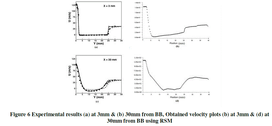 |
| From the obtained results, the 5 equation quadratic pressure strain RSM model seems to closely approximate the experimental results. Hence this model has been chosen for further analyses. |
RESULTS AND DISCUSSIONS |
| The numerical simulations have been done using ANSYS FLUENT 14.0 for all the cases involved in this study. The results comprises of 4 sections. In the first section, the model has been analysed for various values of the velocity ratio. In the subsequent sections, the analysis was done for various values of the velocity and equivalence ratio. In the final section, a comparative study had been done for two shapes of a bluff body with the same frontal area. |
| A. Variation in the inlet velocity ratio |
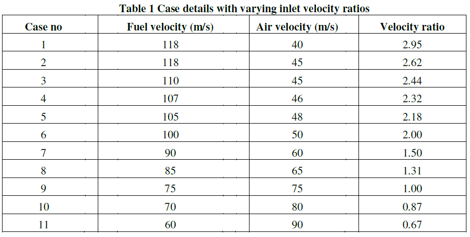
| This section presents the exhaust temperature and CO2 results for the combustion process of methane and air at an equivalence ratio of 0.5. The case details with different velocity values for the fuel and air has been shown in Table 1 below. |
 |
| The average exhaust gas temperature and the mass fraction results for the cases have been summarized in the graph shown in Figure 7. |
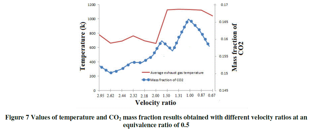 |
| The above result shows that the exhaust gas temperature decreases first and then increases with the decrease of velocity ratio. The lowest temperature is reached at a velocity ratio of 2 and the value was found out to be 658K. Below this point, a uniform temperature of about 1000K is obtained. Thus the optimal combustible velocity ratio is found out to be within 0.6 and 1.8. The mass fraction of CO2 is also seen to be comparatively higher at lower velocity ratios; the maximum being 0.165 at a velocity ratio of 1. This clearly shows that the difference in velocity between the fuel and the air inlets should be low for higher exhaust temperatures and for a better efficient combustion process. |
| B. Variation in the velocity magnitude |
| This section presents the average exhaust gas temperature results at an equivalence ratio of 0.5 and with varying values of the velocity magnitude at a velocity ratio of 1. The velocity values were varied over a wide range from 50m/s to 110m/s. Table 2 summarizes the cases and results. |
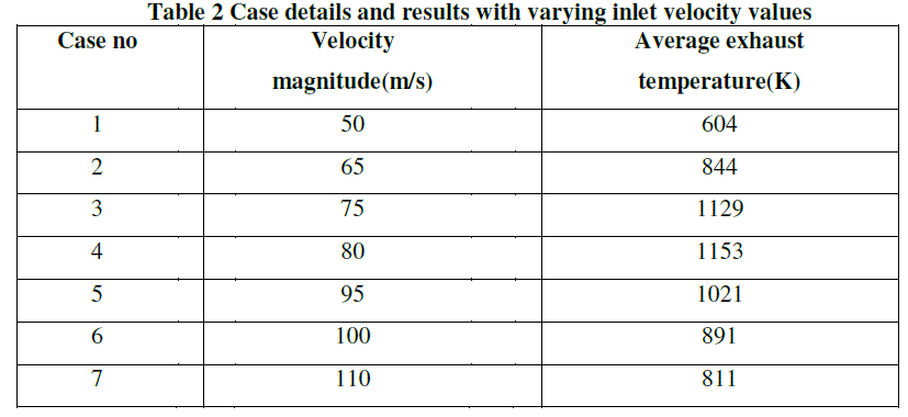 |
| The results show that the average exhaust temperature increases first and then decreases as the velocity increases. The temperature was higher over the range of 70m/s to 95m/s and reaches a maximum of 1153K at 80m/s. |
| C. Variation in the equivalence ratio |
| This section presents the average exhaust gas temperature results for different velocities and equivalence ratios at a velocity ratio of 1. The velocity values were similar to the previous analysis with equivalence ratio of 0.4, 0.5 and 0.6 simulated for all the cases. The graph shown in Figure 8 depicts the results. |
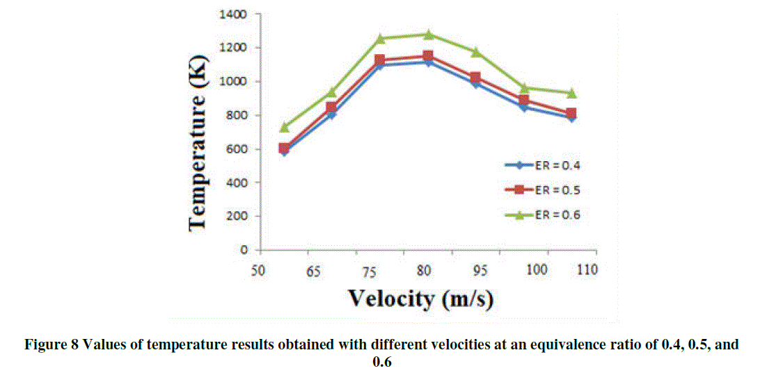 |
| The above graph shows the exhaust gas temperature values for equivalence ratio of 0.4, 0.5, and 0.6. The result shows that comparatively high combustion efficiency can be maintained over the whole equivalence ratio range at a moderate velocity magnitude. The maximum temperature reached for an ER of 0.4 and 0.5 is 1114K and 1153K respectively at 80m/s and 1282K at 75m/s for an ER of 0.6. |
| D. Variation in the bluff body shape |
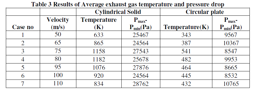
| This section presents the average exhaust gas temperature and pressure drop results for the two bluff body shapes namely (a) circular plate and (b) cylindrical solid shown in Figure 9 and the results are shown in Table 3. |
 |
 |
| The results show that combustion with cylindrical solid bluff body produces temperatures that are almost double to that produced by the circular plate. This is seen by the enormous pressure drop across the solid bluff body which is of the order of 25KPa compared to the 10KPa drop seen around the circular plate. |
CONCLUSION |
| Combustion characteristics of lean methane – air mixture in a combustor with a bluff body stabilized non-premixed flow regime were investigated through simulations which were validated with the experimental results. Effects of the inlet velocity ratio, velocity value, equivalence ratio and the bluff body shape on the combustion efficiency and exhaust gas temperature were examined. The following conclusions have been drawn from this study. |
| 1) It was seen that the RSM turbulent model showed better results compared to the other RANS models for the velocity vectors at critical regions of the flow regime which was necessary for further simulation analysis. |
| 2) This study also reveals that, combustion with cylindrical solid bluff body produces temperatures that are almost double to that produced by the circular plate but with significantly higher pressure drop which is the key driver for drag force. |
| 3) Then it was seen that the inlet velocity ratio and the velocity magnitude also exerts a significant effect on the combustion characteristics. Decreasing the velocity ratio initially shows moderate variation in the temperature. After a particular stage, there seems to be higher temperature values when the ratio is near unity i.e. when the air and fuel are at nearly the same velocity magnitude. Furthermore, with the increase of inlet velocity, the high temperature zone is pushed toward the downstream of the combustor chamber. However, the exhaust gas temperature reaches a peak value at a moderate inlet velocity under a fixed equivalence ratio. |
| These variation tendencies indicate that the combustion characteristics are in fact determined by many factors like disorderliness, heat losses, recirculation zones, momentary pressure drops, turbulence and their complicated interactions. |
References |
|