ISSN ONLINE(2319-8753)PRINT(2347-6710)
ISSN ONLINE(2319-8753)PRINT(2347-6710)
Vivekanand s Gogi1, Rohith D2, Shashi Kiran K3, Suhail M Shaikh4
|
| Related article at Pubmed, Scholar Google |
Visit for more related articles at International Journal of Innovative Research in Science, Engineering and Technology
Facilities layout is a systematic and functional arrangement of different departments, machines, equipments and services in a manufacturing industry. It is essential to have a well developed plant layout for all the available resources in an optimum manner and get the maximum out of the capacity of the facilities. The efficiency of production depends on how well the various machines, services production facilities and employee’s amenities are located in a plant. This research paper aims to study and improve the current plant layout and are analysed & designed by using string diagram. An Attempt is made to simulate the current and proposed factory layout by using ARENA software. Efficiency of the current & proposed plant layout are calculated.
Keywords |
| Facilities Layout; Layout Design; Simulation; Redesign facility layout; Material flow. |
INTRODUCTION |
| Increasing global competition has evolved a manufacturing environment which gleans vast product configuration, reduced lead times, and increased standards of quality and competitive costs. In parallel with a rising trend toward globalization, these manufacturing facilities must be designed to cater for new challenges to survive and grow in the marketplace. Plant layout is the arrangement of desired machinery and equipment of a plant in a way which will permit the easiest flow of materials, at the lesser cost with minimum handling, in processing the product from the raw materials to the dispatched of the finished product. The research paper presents solving an industrial problem using the principle of string diagram and simulation software. |
| 1. The string diagram is a simple tool for analyzing and designing work spaces in such a way that the movement of material, men, equipment etc... Are minimized. |
| 2. The string diagram is a form of flow diagram, in which a thread is used to measure the distance of material, men movement. It is important that the string diagram drawn to an exact scale. |
| 3. The string diagram is carried out in exactly the same way as all other method studies, by recording all the relevant information and facts from direct observation. |
| A string diagram can be used to plot the movements of equipment, material, and essentially when a work study person wants to find out how far the materials travel. A simulation study was under taken to find out the overall efficiency of the plant. |
II. LITERATURE SURVEY |
| Efficiency of a plant layout can be increased by redesigning the plant layout using String diagram and Systematic layout planning. These fundamental guidelines, when designing a plant layout are to be considered. It is the basic set of guidelines to be followed during layout design and redesign. It provides basic details about the flow of material through the shop floor and the interrelation of various activities. It also explains about the material flow and layout design using string diagram. [1] |
| One such research explains about the planning methods and procedures for various types of production facility. The type of layout designs to be adopted and implemented during layout design and has also provided the key elements for layout design. The type of flow of material and the requirement of basic process of redesign is also explained. [2] |
| Many industries use activity relationship charts (ARC) and diagrams for layout redesign and layout planning. The use of activity relationship diagram in designing a layout has provided a basic step for layout planning. [3] |
| Another research focuses on the problems occurred during designing flexible plant layouts for manufacturing facilities where product demands are subject to variability. A flexible layout is one that maintains low material handling costs despite fluctuations in the product demand levels. [4] |
| A research conducted in an industry explains about the warehouse redesign of a manufacturing plant Layout and also the problems faced during the redesign of the layout. [5] |
| A case study explains an in detailed redesign of an existing production facility. The design of production facility differs from that of manufacturing layout. The analysis of the capacity of the equipment is done, then by using this analysis a group technology is used to make different type of parts in a layout and identification of a material handling solution for a material flow. [6] |
| A research conducted to identify and improve the plant layout of pulley’s factory to eliminate obstructions in material flow and thus obtain maximum productivity. The present plant layout and the operation process of each section (i.e. sand mould, core ware house, core making, disassembly surface finishing, furnace, and inspection sections) have been investigated and a new layout has been designed. [7] |
| Semi- heuristic optimization algorithm (CRAFT) for designing optimal plant layouts in process focused manufacturing/service facilities are also been explained. The proposed algorithm marries the well-known CRAFT (Computerized Relative Allocation of Facilities Technique) with the Hungarian assignment algorithm. Being a semiheuristic search, our algorithm is likely to be more efficient in terms of computer CPU engagement time as it tends to converge on the global optimum faster than the traditional CRAFT. [8] |
III. GENESIS OF PROBLEM |
| The plant layout redesign for increase in efficiency was considered necessary because of the following reasons: |
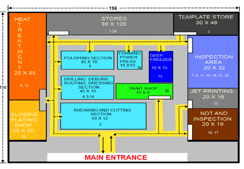
| 1. Improper material flow through the shop floor i.e., the current plant layout was not designed according to the process flow given by DGCA. |
| 2. Extended transportation time for material transfer. The sheet metal section had issues to be handled. Based on the discussion with the manager and supervisors and direct observation by the team, the following problem surface was about non value added operations in the process. |
IV. CONSTRAINTS |
| 1. Stores and heat treatment sections should not be interchanged or changed. |
| 2. Dimensions of current departments and aisle should not be changed. |
V. OBJECTIVES |
| The problem genesis led to the formulation of the following objectives: |
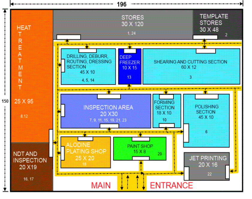
| 1. To study the current flow pattern and relation of overall plant layout and develop a new plant layout. |
| 2. Relocating the workstations for simpler flow and reduction in check points. |
| 3. To improve the efficiency of the plant layout using simulation. |
VI. TOOLS AND TECHNIQUES |
| The various tools and techniques used for plant layout redesign are: |
| 1. Checklist: The layout evaluation checklist is used to identify the key problem areas in the present layout. |
| 2. String diagram: The string diagram is one of the simplest techniques of method study for recording and examining movement of workers and materials. It is a tool for analyzing and designing work spaces in such a way that the movement of material, men, equipment etc... During a specified sequence of events. The string diagram is thus a form of flow diagram. In this a thread is used to measure distance. Hence, it is necessary that the string diagram be drawn correctly to scale It is most often used to supplement the flow process chart. A string diagram can be used to plot the movement of material and this is done especially when a work study person wants to find out easily just how far the materials travel. The complete plan containing all the equipment’s and doorways, pillars and partitions, which affect path of movement, are drawn to scale. A measured length of thread is then taken and tied round the pins at the string points of movement. Thus the string diagram is a useful aid in explaining proposed changes to company management, production supervisors and employees. |
| 3. Outline process chart: An outline process chart is a process chart giving an overall picture by recording in sequences only the main operations and inspections. In an outline process chart, only the principle operations are carried out and the inspections made to ensure the effectiveness are recorded, irrespective of who does them and where they performed. In preparing such a chart, only the symbols for “operation” and “inspection” are necessary. In addition to the informed given by the symbols and their sequences, a brief note of the nature of each operation or inspection is made beside the symbol, and are allowed to be added. |
| 4. Flow process chart: It is a process chart used for setting out the sequence of the flow of a product or a procedure by recording all events under review using appropriate process chart symbols. |
VII. DATA COLLECTION |
| 1. Existing layout: The area occupied by the machines, aisles, work-in-progress, storage areas, raw material areas and finished goods area, etc. was measured and scaled drawings of the floor plans for the building were made. MS office and Auto cad was used for the purpose. |
| 2. Outline Process Chart: Outline process chart (OPC) was used to get and overall picture of primary activities OPC for the studied process. |
| 3. Flow Process Chart: Flow Process Chart was used to document the detailed sequence of operations. |
| 4. String Diagrams: String Diagrams were used to trace and measure the path of material. String diagrams were made both by hand and by software, MS office using Auto cad. |
| 5. Simulation: Time taken by each machine to process the component is collected and recorded. The standard time for each process is also recorded. These data are used in simulation in order to find out the overall utilization of the plant. The simulation model is shown in the figure below. |
VIII. RESULTS |
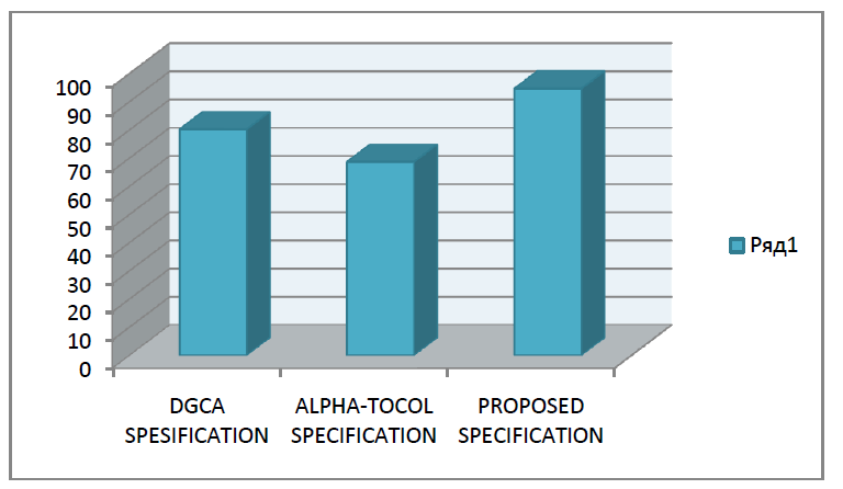
| The proposed plant layout efficiency is 126.05% which is greater than the efficiency of the current plant layout i.e., 68.02%. The efficiency improvement of the plant was increased up to 85.31%. And the reduction in transportation length of 46% was achieved. |
 |
 |
 |
 |
 |
 |
 |
IX. CONCLUSION |
| This research paper has provided a good exposure to facility planning and layout designs for the improvement of the efficiency. The choice of which type of facility layout to adopt can have a significant impact on the long-term success of a firm. This decision, therefore, should not be considered lightly, but only after a through analysis of the operational requirements has been completed. A major issue to be addressed in facility layout decisions in manufacturing is: How flexible should the layout be in order to adjust to future changes in product demand and product mix. The study of layout has become extremely important. The most common objective of layout design, that is to minimize distance travelled, is not always suitable for all the manufacturing industries. Congestion in a specific area may have to be tolerated while maintaining minimum separation between facilities. Instead of criterion of minimizing total distance travelled, one may wish to minimize the total distance of the material travelled. |
ACKNOWLEDGEMENT |
| We express our profound thanks to Alpha-Tocol Engineering services Pvt Ltd., and R.V.College of Engineering for having provided with the opportunity to undertake research work as a part of our engineering curriculum. We would like to thank Dr. K. N. Subramanaya, Vice-Principal, R V College of Engineering, for his support and encouragement. We would like to thank Dr. N. Narahari Head of the Department of Industrial Engineering and Management for the boundless words of encouragement and confidence that he has provided us with the throughout. We take this opportunity to express our gratitude to Mr.Rajasekaran, CEO; Alpha-Tocol Engineering services Pvt Ltd., for providing us with the chance to carry out research work at Alpha-Tocol Engineering services Pvt Ltd. He has fervently supported our activities, and it could have been impossible to confidently propose a new layout without his enthusiastic encouragement. |
References |
|